skip to main |
skip to sidebar


Above top is the pinout diagram for the 24xx256, & below that is how the 24LC08 is connected to the Arduino. The pinout's the same anyway..
Note that Analog pins 4 & 5 are used for the I2C communication, so they can't be used for any other purpose.
Pull-up resistors R1 & R2 are 10 kilOhms.
It's all fairly simple really (she says, crossing her fingers & toes)..
Hard-wiring a shield is now fairly simple - i just have to Stop Procrastinating!!
The other pins can be used for breadboarded inputs & outputs - for inputs from the 'Great Weekend Datalogging Project' - more about that later..
This program has been revisited.

The Fritzing diagram for my Minor Project shouldn't be very complicated - it's basically connecting two external 8-pin DIP-packaged external EEPROM chips to the basic Arduino board so that write/read operations can proceed.
On the left is the 24LCxx pinout table.
This is nice because it means i can swap the
24LC08 chips i have now for, say, 24LC256 chips, & all i need to do is change a bit of software!
 Just above is how you connect several external EEPROMs on the same I2C bus - each has a connection to the SCL line & the SDA line..
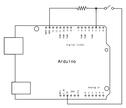
 The circuit is quite simple - pin 2 is pulled down to 0V through the 10k pull-down resistor, until the button is closed. This pulls pin 2 up to +5V, & this causes pin 13 to go HIGH & light up the on-board LED
.
The actual push-button has 4 terminals, but they are paired, (as is evident on the breadboard).