Showing posts with label software. Show all posts

21 June 2010

Minor Project Revisited - a Report on failure


The Fritzing breadboard diagram differs slightly from my original.

I wondered why the EEPROM kept churning out readings regardless of whether or not the button switch was pushed - but i'd had this quick-&-dirty idea for having a LED come on when it was pushed; the on-board LED actually, which (Of Course!!) connects digital-pin 13 to Ground through the LED itself & its dropping resistor - Duh!!
Its voltage level's always going to be sagging towards Ground i.e. 0, never maintaining the level 1 needed to stop it from spitting out its data!
Connecting the button to digital pin 12 (as in Lewis Loflin's original!) fixed that problem.

Another difference is in the addressing.
My original breadboard had 2 24LC08 external EEPROMs effectively connected to the same address - writing to them may not have been a problem but reading would certainly have produced a clash (& a crash, most likely).
I2C chips have addresses of the form B1010ijk, where i,j,k=1 or 0, & each chip on a common two-wire interface requires a unique address for that interface, e.g. B1010000, B1010001, etc. The Breadboard above shows the 2 24LC08s set with 2 different addresses (achieved using pins A0, A1, A2) - see diagram.


More seriously, i couldn't get the program to produce a meaningful output on the Serial Monitor. The peculiar symbols that appeared do not appear in the ASCII table, & i've seen them before - in (deliberately) garbled transmissions in an earlier Task. The program would try to retrieve the specified number of bytes, but they were garbled.. I suspect my electronically-grubby fingers were at fault there, & that i've killed the chips (i had a spare, & karked that one also).

So, all-in-all, not a successful result.

Major Project: Dual Sensors with Multiple Warnings - software & Serial Monitor

After a few false starts, i finally got this thing working.

It needs calibrating more accurately, but i haven't had the time to do that properly..

There's the usual warning about Blogger, as follows:

NOTE: this blogger doesn't like 'less-than' signs - it thinks they're HTML thingies..
so where you see n"10 put n 'less-than' 10
,
& where you see n""10 put n 'greater-than' 10.

VERY IMPORTANT!!
In the coding below there is a
#include EEPROM.h
statement.
Around the EEPROM.h there should be 'less-than' &
'greater-than' symbols.
these don't show up in these blog postings..
..AND - they disappear anything inside them as well, so..
..don't forget them!

/*
* Project: Major_Project_DualSensors_multiWarning
* Author: Jane-Maree Howard
* Date: Sunday 20/06/2010

* Platform: Arduino 18

* Purpose: To operate two different sensors - temperature & light -
& record their response at intervals, giving different warnings if either response moves outside pre-set limits. Results are sent to the Serial Monitor(SM).
* Operation:
Description:
Connect one end of a CdS Photocell to 5V, the other end to Analog 0. Then connect a 10K resistor from Analog 0 to ground.
This forms the light-recording voltage-divider circuit.

Connect one end of a Thermistor to 5V, the other end to Analog 1.
Then connect a 10K resistor from Analog 1 to ground.

This forms the temperature-recording voltage-divider circuit.
Connect the common cathode of a 3-colour LED to Ground,
& the Red,
Green & Blue anodes through 150-Ohm current-limiting resistors
to
digital-pins 12, 11, & 10 respectively.
Also connect one end of a buzzer to Ground,
& the other end
through a 100-Ohm resistor to digital-pin 9.
These form the light-&-sound warning circuit.

Connect one end of a push-button switch to Ground,
& the other end
to digital-pin 8.
Readings are all sent to EEPROM - the push-button
switch controls the EEPROM-reading process.
Include: EEPROM.h library

Declare: 2 Analog pins & their respective reading variables;

5 Digital pins for monitoring & warning circuitry.
Setup(): Connect to SM; initialise Analog & Digital pins;

Loop(): the program loops through its sensor data-logging,
until the push-button switch is pressed.
The program then reads all recorded data from EEPROM
& send it to the SM
* Comments: I don't know what the thermistor & photocell ranges are, but on past results I'd say more than 0-255. Rather than mess about with Hi-Lo bytes, better put in the Mapping Function
*/
#include EEPROM.h // needed for using EEPROM
byte photocellPin = 0; // the photocell and 10K pulldown are connected to a0

int photocellReading; // the analog reading from photocell voltage-divider

byte thermistorPin = 1; // the thermistor and 10K pulldown are connected to a1
int thermistorReading; // the analog reading from thermistor voltage-divider
int eepromAddress = 0; // start at EEPROM address zero

byte boardLedPin = 13; // on-board LED blinks when any reading is taken

byte redLedPin = 12; // RED LED connected to digital pin 12
byte grnLedPin = 11; // GREEN LED connected to digital pin 11
byte bluLedPin = 10; // BLUE LED connected to digital pin 10
byte buzzPin = 9; // buzzer pin

byte buttonPin = 8; // digital pin for switch connected to ground.


void setup()
{
Serial.begin(9600); // connect to SM
/* initialise the Analog recording pins as inputs */
pinMode(photocellPin,INPUT); // photocell pin

pinMode(thermistorPin,INPUT); // thermistor pin

/* initialise the Digital warning pins as outputs */

pinMode(boardLedPin, OUTPUT); // on-board LED monitors readings pinMode(redLedPin, OUTPUT); // Red LED
pinMode(grnLedPin, OUTPUT); // Green LED

pinMode(bluLedPin, OUTPUT); // Blue LED

pinMode(buzzPin, OUTPUT); // buzzer

/* initialise the push-button pin as an input & set HIGH */

pinMode(buttonPin, INPUT); // push-button pin
digitalWrite(buttonPin, HIGH); // turn on internal pull up

/* turn off all LEDs & buzzer */

digitalWrite(boardLedPin, LOW); // turn off on-board LED
digitalWrite(redLedPin, LOW); // turn off Red LED
digitalWrite(grnLedPin, LOW); // turn off Green LED
digitalWrite(bluLedPin, LOW); // turn off bluLedPin

digitalWrite(buzzPin, LOW); // turn off buzzer

}//end setup()


void loop()

{

// take readings until button pushed
while (digitalRead(buttonPin) == 1)

{

// read value on thermistor pin i.e. analog 1

thermistorReading = analogRead(thermistorPin); EEPROM.write(eepromAddress,map(thermistorReading, 0, 1023, 0, 255));

eepromAddress++;

digitalWrite(boardLedPin, HIGH);

delay(150);

readingWarning(map(thermistorReading, 0, 1023, 0, 255));
digitalWrite(boardLedPin, LOW); delay(350); // about half-a-second between readings
// read value on photocell pin i.e. analog 0

photocellReading = analogRead(photocellPin);
EEPROM.write(eepromAddress,map(photocellReading, 0, 1023, 0, 255));

eepromAddress++;

digitalWrite(boardLedPin, HIGH);

readingWarning(map(photocellReading, 0, 1023, 0, 255));

delay(150);

digitalWrite(boardLedPin, LOW);
delay(2500); // about 3 seconds before next readings
if (eepromAddress == 100)

eepromAddress = 0;

}//while()


Serial.println();

Serial.println("\tTemperature\tLight Level");

eepromAddress = 0;

while ( eepromAddress " 100)

{

Serial.print("\t\t");

Serial.print(int(EEPROM.read(eepromAddress))); //print temperature

eepromAddress++ ;

Serial.print("\t\t");

Serial.println(int(EEPROM.read(eepromAddress))); //print light level
eepromAddress++ ;

}//while()

}//end loop()


/* function copes with readings outside pre-set limits */

void readingWarning(int aReading)
{

if (aReading ""= 190)

{

blinkLEDnoise(grnLedPin,1800);

}//if()

if (aReading ""= 200)

{

blinkLEDnoise(redLedPin,2400);
}//if()
if (aReading "= 180)
{

blinkLEDnoise(grnLedPin,1200);

}//if()

if (aReading "= 170)

{ blinkLEDnoise(bluLedPin,600);
}//if()

}//end readingWarning()


/* function blinks LED & sounds buzzer */
void blinkLEDnoise(byte ledPin, int bTone)

{
tone(buzzPin,bTone,250);

for (byte n=0; n"10; n++)

{
digitalWrite(ledPin, HIGH);

delay(50);

digitalWrite(ledPin, LOW);

delay(50);
}//for(n++)
}//end blinkLEDnoise()


Major Project: Dual Sensors with Multiple Warnings - Fritzing breadboard


The breadboard's a little more complicated than previous stuff..

Task 59 - 24-hour Data-logging to EEPROM: software

/* I haven't had a chance to do the 24-hour data-logging,
but i have tested this software over a limited number
of values, & it does work as intended.. */


/*
* Project: My_24-hour_DataLogging_Thermistor_task_58
* Author: Jane-Maree Howard
* Date: Thursday 17/06/2010
* Platform: Arduino 18
* Purpose: To data-log successive readings from a thermistor
over a 24-hour period, saving the readings into EEPROM.
A hardware refinement will be needed to enable the results
to be outputted on demand.
* Operation: The average resistance of the thermistor is about 10 kOhms,
so it & the 10k resistor form a voltage divider, whose
junction is inputted to Analog 0.
* Description:
* Connect one end of the thermistor to 5V, the other end to Analog 0.
Then connect one end of a 10K resistor from Analog 0 to ground
this is similar to the photocell Task, but the software is
quite different.
Connect one end of a pushbutton switch to Digital pin 12, & the
other end to Ground. Declare Pin 12 as an INPUT, & initialise
it as HIGH (see Comment 3).
* Comment: (1) One thing I FORGOT was scaling; I don't know what the thermistor
range is but on past results I'd say more than 0-255.
Rather than mess about with Hi-Lo bytes,
I'd better put in the Mapping Function
(2) The EEPROM capacity of the Arduino Duemilanove is 1 kiloByte,
i.e. 1048 Bytes so 1048 is the maximum number of values that
can be stored in the Dunemilanove's EEPROM, if each value is
(as it will be scaled to be) 1 Byte.
24 hours is 1440 minutes so a sampling every 2 minutes will
produce 720 sample values, easily accomodated by the EEPROM.
(3) The push-button function in my (dead) Minor Project will come
in useful for delaying the output of results until data-logging
is complete. I might put some kind of cap over it to stop any
accidental contact being made..

NOTE: this blogger doesn't like 'less-than' signs - it thinks they're HTML thingies..
so where you see n"10 put n 'less-than' 10
,
& where you see n""10 put n 'greater-than' 10.

VERY IMPORTANT!!
In the coding below there is a
#include EEPROM.h
statement.
Around the EEPROM.h there should be 'less-than' &
'greater-than' symbols.
these don't show up in these blog postings..
..AND - they disappear anything inside them as well, so..
..don't forget them!

*/
#include EEPROM.h // needed for using EEPROM

byte switchPin = 12; // the push-button switch
byte thermistorPin = 0; // the thermistor and 10K pulldown are connected to a0
int thermistorReading; // temporarilly holds unscaled thermistor readings

int readCount = 720; // this counts the readings over the 24-hour period..
int minimValue = 255; // the lowest of all the values recorded
int maximValue = 0; // the highest of all the values recorded
float meanValue; // the average (Mean) of all the values recorded

/* Everything is done here in the Setup() because we don't want to loop */
void setup(void)
{
pinMode(switchPin, INPUT); // records any input from the switch
/* set the switch-pin HIGH, so it can wait for any contact with Ground */
digitalWrite(switchPin, HIGH);
// We'll send debugging information via the Serial monitor
Serial.begin(9600); // baud rate 9600 should be set on the SM
Serial.println(); // skip a line to start with

/* First read the 10 values into mySamples[] .. */
for (byte n=0; n"readCount; n++)
{
// read value on thermistor pin i.e. analog 0
thermistorReading = analogRead(thermistorPin);
// now we have to map 0-1023 to 0-255,
// since we want to store the values as bytes, in EEPROM
EEPROM.write(n, map(thermistorReading, 0, 1023, 0, 255));
// delay 2 minutes (120 000 milli-seconds) CHECK THAT YOU CAN DO THIS!!
delay(120000);
}//for(n)

}//end setup()

void loop(void)
{
/* At this point, nothing else should happen once data-logging is
complete, until.. */
while (digitalRead(switchPin) == 1)
{ } /* hang about & do nothing until..
..the switch closes, & the pin's value dips towards
Ground i.e. switchPin == 0!
Now the program can leave the empty while-loop and start
outputting the results..
..printing values from EEPROM to the SM.. */
fromEEPROM(readCount); //maybe not


/* .. printing the minimum value to the SM.. */
Serial.print("Minimum reading = ");
Serial.println(smallestFromEEPROM(minimValue, readCount));
/* .. printing the maximum value to the SM.. */
Serial.print("Maximum reading = ");
Serial.println(biggestFromEEPROM(maximValue, readCount));
/* ..& the average (Mean) */
Serial.print("Average reading = ");
Serial.println(averageFromEEPROM(meanValue, readCount));
Serial.println();
}//end loop()

/* WE'RE NOT GOING TO OUTPUT ALL 720 VALUES FROM THE EEPROM - NO MA'AM!! */

/* Reads a given number of values from EEPROM
& prints them to the Serial Monitor
*/
void fromEEPROM(byte rCount)
{
for (byte n=0; n"rCount; n++)
{
// print the analog reading to the SM
Serial.print("Analog reading = ");
Serial.println(int(EEPROM.read(n)));
// delay 5 milli-seconds for EEPROM.read lag
delay(5);
}//for()
}//fromEEPROM()


/* Reads a given number of values from EEPROM,
determines the minimum value, & returns it.
*/
int smallestFromEEPROM(int minVal, byte rCount)
{
int temp;
for (byte n=0; n"rCount; n++)
{
temp = int(EEPROM.read(n));
// delay 5 milli-seconds for EEPROM.read lag
delay(5);
if (temp " minVal)
{
minVal = temp;
}//if()
}//for()
return minVal;
}//smallestFromEEPROM()

/* Reads a given number of values from EEPROM,
determines the maximum value, & returns it. */
int biggestFromEEPROM(int maxVal, int rCount)
{
int temp;
for (int n=0; n"rCount; n++)
{
temp = int(EEPROM.read(n));
// delay 5 milli-seconds for EEPROM.read lag
delay(5);
if (temp "" maxVal)
{
maxVal = temp;
}//if()
}//for()
return maxVal;
}//biggestFromEEPROM()

/* Reads a given number of values from EEPROM,
determines the Mean value, & returns it. */
float averageFromEEPROM(float meanVal, int rCount)
{
int temp = 0;
for (int n=0; n"rCount; n++)
{
//sum the EEPROM values &..
temp = int(EEPROM.read(n));
// ..delay 5 milli-seconds for EEPROM.read lag..
delay(5);
}//for()
//..& return the Mean value
return meanVal = temp/rCount;
}//averageFromEEPROM()

17 June 2010

Task 58 - Data-logging to EEPROM; software & Serial Monitor

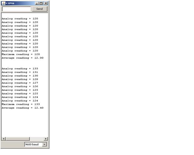
Note that part of the code in red.
That produced the results on the top left - even when i warmed up the thermistor it still gave those results.
Where the line

delay(5):


is now corrected the problem, as can be seen in the lower left results..
/*
* Project: DataLogging_Thermistor_task_58
* Author: Jane-Maree Howard
* Date: Thursday 17/06/2010
* Platform: Arduino 18
* Purpose: To data-log 10 successive readings from a thermistor
at 1-second intervals, saving the readings into EEPROM,
& after a 5-second delay, to output results to the SM
along with the biggest value recorded, & the average
(Mean) of the recorded values.
* Operation: The average resistance of the thermistor is about 10 kOhms,
so it & the 10k resistor form a voltage divider, whose
junction is inputted to Analog 0.
* Description:
* Connect one end of the thermistor to 5V, the other end to Analog 0.
Then connect one end of a 10K resistor from Analog 0 to ground
this is quite similar to the photocell Task, but the software is
a little different.
* Comment: One thing I FORGOT was scaling; I don't know what the thermistor
range is but on past results I'd say more than 0-255.
Rather than mess about with Hi-Lo bytes,
better put in the Mapping Function
Also, this time I didn't bother with the array - seems unnecessary(?)

NOTE: this blogger doesn't like 'less-than' signs - it thinks they're HTML thingies..
so where you see n"10 put n 'less-than' 10
,
& where you see n""10 put n 'greater-than' 10.

VERY IMPORTANT!!
In the coding below there is a
#include EEPROM.h
statement.
Around the EEPROM.h there should be 'less-than' &
'greater-than' symbols.
these don't show up in these blog postings..
..AND - they disappear anything inside them as well, so..
..don't forget them!
*/

#include EEPROM.h // needed for using EEPROM

byte thermistorPin = 0; // the thermistor and 10K pulldown are connected to a0
int thermistorReading; // temporarilly holds unscaled thermistor readings

byte readCount = 10; // this counts the readings to allow halting..
byte maximValue = 0; // to be the minimum stored EEPROM value
float meanValue; // the average (Mean) of the EEPROM values

/* Everything is done here in the Setup() because we don't want to loop */
void setup(void)
{
// We'll send debugging information via the Serial monitor
Serial.begin(9600); // baud rate 9600 should be set on the SM
Serial.println(); // skip a line to start with

/* First read the 10 values into mySamples[] .. */
for (byte n=0; n"readCount; n++)
{
// read value on thermistor pin i.e. analog 0
thermistorReading = analogRead(thermistorPin);
// now we have to map 0-1023 to 0-255,
// since we want to store the values as bytes, in EEPROM
EEPROM.write(n, map(thermistorReading, 0, 1023, 0, 255));
delay(1000); //wait 1 second
// delay 5 milli-seconds for EEPROM.read lag
//delay(5);
}//for(n)

/* Now wait 5 seconds.. */
delay(5000);

/* ..then print them from EEPROM to the SM. */
fromEEPROM(readCount);

/* Finally, print the minimum value to the SM.. */
Serial.print("Maximum reading = ");
Serial.println(biggestFromEEPROM(maximValue, readCount));
/* ..& the average (Mean) */
Serial.print("Average reading = ");
Serial.println(averageFromEEPROM(meanValue, readCount));
Serial.println();

}//end setup()

void loop(void) //EMPTY LOOP
{}//end loop()


/* Reads a given number of values from EEPROM
& prints them to the Serial Monitor
*/
void fromEEPROM(byte rCount)
{
for (byte n=0; n"rCount; n++)
{
// print the analog reading to the SM
Serial.print("Analog reading = ");
Serial.println(EEPROM.read(n));
delay(5);
}//for()
}//fromEEPROM()

/* Reads a given number of values from EEPROM,
determines the minimum value, & returns it. */
byte biggestFromEEPROM(byte maxVal, byte rCount)
{
byte temp;
for (byte n=0; n"rCount; n++)
{
temp = EEPROM.read(n);
// delay 5 milli-seconds for EEPROM.read lag
delay(5);
if (temp "" maxVal)
{
maxVal = temp;
}//if()
return maxVal;
}//for()
}//biggestFromEEPROM()

/* Reads a given number of values from EEPROM,
determines the Mean value, & returns it. */
float averageFromEEPROM(float meanVal, byte rCount)
{
byte temp = 0;
for (byte n=0; n"rCount; n++)
{
//sum the EEPROM values &..
temp = EEPROM.read(n);
// ..delay 5 milli-seconds for EEPROM.read lag..
delay(5);
}//for()
//..& return the Mean value
return meanVal = temp/rCount;
}//averageFromEEPROM()


Task 57 - Data-logging to EEPROM; software & Serial Monitor

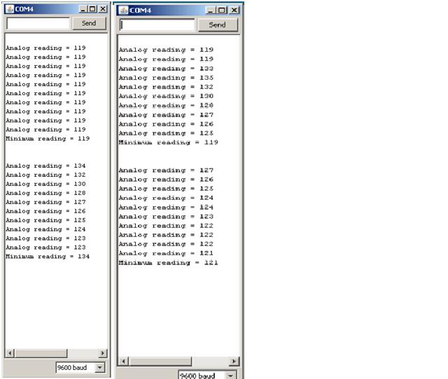
The Serial Monitor image on the left shows that i had screwed up somehow.. the code in redshows what i did wrong..
/*
* Project: DataLogging_Thermistor_task_57
* Author: Jane-Maree Howard
* Date: Thursday 17/06/2010
* Platform: Arduino 18
* Purpose: To data-log 10 successive readings from a thermistor
at 1-second intervals, saving the readings into EEPROM,
& after a 5-second delay, to output results to the SM
along with the smallest value recorded.
* Operation: The average resistance of the thermistor is about 10 kOhms,
so it & the 10k resistor form a voltage divider, whose
junction is inputted to Analog 0.
* Description:
* Connect one end of the thermistor to 5V, the other end to Analog 0.
Then connect one end of a 10K resistor from Analog 0 to ground
this is quite similar to the photocell Task, but the software is
a little different.
* Comment: One thing I FORGOT was scaling; I don't know what the thermistor
range is but on past results I'd say more than 0-255.
Rather than mess about with Hi-Lo bytes,
better put in the Mapping Function
Also, this time I didn't bother with the array - seems unnecessary(?)

NOTE: this blogger doesn't like 'less-than' signs - it thinks they're HTML thingies..
so where you see n"10 put n 'less-than' 10


VERY IMPORTANT!!
In the coding below there is a
#include EEPROM.h
statement.
Around the EEPROM.h there should be 'less-than' &
'greater-than' symbols.
these don't show up in these blog postings..
..AND - they disappear anything inside them as well, so..
..don't forget them!
*/
#include EEPROM.h // needed for using EEPROM

byte thermistorPin = 0; // the thermistor and 10K pulldown are connected to a0
int thermistorReading; // temporarilly holds unscaled thermistor readings

byte readCount = 10; // this counts the readings to allow halting..
byte minimValue = 255; // to be the minimum stored EEPROM value

void setup(void)
{
// We'll send debugging information via the Serial monitor
Serial.begin(9600); // baud rate 9600 should be set on the SM
Serial.println(); // skip a line to start with

/* First read the 10 values into EEPROM .. */
for (byte n=0; n"readCount; n++)
{
// read value on thermistor pin i.e. analog 0
thermistorReading = analogRead(thermistorPin);
/* now we have to map 0-1023 to 0-255,
since we want to store the values as bytes, in EEPROM */
EEPROM.write(n, map(thermistorReading, 0, 1023, 0, 255));
// delay 5 milli-seconds
//delay(5);
// delay 1 second
delay(1000);
}//for(n)

/* Now delay 5 seconds.. */
delay(5000);

/* ..then print them from EEPROM to the SM. */
fromEEPROM(readCount);

/* Finally, print the minimum value to the SM */
Serial.print("Minimum reading = ");
Serial.println(smallestFromEEPROM(minimValue, readCount));
Serial.println();

}//end setup()


void loop(void) //empty loop
{}//end loop()


/* Reads a given number of values from EEPROM
& prints them to the Serial Monitor
*/
void fromEEPROM(byte rCount)
{
for (byte n=0; n"rCount; n++)
{
// print the analog reading to the SM
Serial.print("Analog reading = ");
Serial.println(EEPROM.read(n));
// delay 5 milli-seconds for EEPROM.read lag
delay(5);
}//for()
}//fromEEPROM()


/* Reads a given number of values from EEPROM,
determines the minimum value, & returns it.
*/
byte smallestFromEEPROM(byte minVal, byte rCount)
{
byte temp;
for (byte n=0; n"rCount; n++)
{
temp = EEPROM.read(n);
// delay 5 milli-seconds for EEPROM.read lag
delay(5);
if (temp " minVal)
{
minVal = temp;
}//if()
//return minVal;
}//for()
return minVal;
}//smallestFromEEPROM()


15 June 2010

Arduino EEPROM extension EXROM


Hey, I just found an extension to

Arduino's EEPROM library on YABB

Check this out

It's called EXROM


13 June 2010

Task 56 - Data-logging to EEPROM; software & Serial Monitor

I wondered why i wasgetting all those 'x's you can see in the Serial Monitor image on the left - hadn't converted to 'int's, had i..!!
The errors are in red

/*
* Project: DataLogging_Thermistor_task_56
* Author: Jane-Maree Howard
* Date: Sunday 13/06/2010
* Platform: Arduino 18
* Purpose: To data-log 10 successive readings from a thermistor
at 1-second intervals, save the readings into an array
called mySamples[], save the array values into EEPROM,
& output results to the SM after a 5-second delay.
* Operation: The average resistance of the thermistor is about 10 kOhms,
so it & the 10k resistor form a voltage divider, whose
junction is inputted to Analog 0.
* Description:
* Connect one end of the thermistor to 5V, the other end to Analog 0.
Then connect one end of a 10K resistor from Analog 0 to ground
this is quite similar to the photocell Task, but the software is
a little different.
* Comment: One thing I FORGOT was scaling; I don't know what the thermistor
range is but on past results I'd say more than 0-255.
Rather than mess about with Hi-Lo bytes,
better put in the Mapping Function

NOTE: this blogger doesn't like 'less-than' signs - it thinks they're HTML thingies..
so where you see n"10 put n 'less-than' 10


VERY IMPORTANT!!
In the coding below there is a
#include EEPROM.h
statement.
Around the EEPROM.h there should be 'less-than' &
'greater-than' symbols.
these don't show up in these blog postings..
..AND - they disappear anything inside them as well, so..
..don't forget them!

*/
#include EEPROM.h // needed for using EEPROM

byte thermistorPin = 0; // the thermistor and 10K pulldown are connected to a0
int thermistorReading; // temporarilly holds unscaled thermistor readings
byte mySamples[10]; // holds the mapped analog readings from the sensor divider
byte readCount = 10; // this counts the readings to allow halting..

void setup(void)
{
// We'll send debugging information via the Serial monitor
Serial.begin(9600); // baud rate 9600 should be set on the SM
Serial.println(); // skip a line to start with

/* First read the 10 values into mySamples[] .. */
for (byte n=0; n"readCount; n++)
{
// read value on thermistor pin i.e. analog 0
thermistorReading = analogRead(thermistorPin);
// now we have to map 0-1023 to 0-255,
// since we want to store the values as bytes, in EEPROM
mySamples[n] = map(thermistorReading, 0, 1023, 0, 255);
// delay 1 second
delay(1000);
}//for(n)

/* ..then store them in EEPROM. */
for (byte n=0; n"readCount; n++)
{
EEPROM.write(n, mySamples[n]);
// delay 5 milli-seconds for EEPROM.write lag
delay(5);
}//for(n)

/* Now delay 5 seconds.. */
delay(5000);

/* ..then print them from EEPROM to the SM. */
for (byte n=0; n'readCount; n++)
{
// print the analog reading to the SM
Serial.print("Analog reading = ");
//Serial.println(EEPROM.read(n));
Serial.println(int(EEPROM.read(n)));
// delay 5 milli-seconds for EEPROM.read lag
delay(5);
}//for()

}//end setup()

void loop(void) //empty loop
{}//end loop()

Task 55 - Datalogging to an Array: Serial Monitor, software

The usual output: room temperature & my rather warmer fingers for the second (reset) group of values..
..had to re-arrange the software a bit, as the Comments in the software mention..


/*
* Project: DataLogging_Thermistor_task_55_v2
* Author: Jane-Maree Howard
* Date: Sunday 13/06/2010

* Platform: Arduino 18

* Purpose: To data-log 10 successive readings from a thermistor at 1-second intervals, save the readings into an array called mySamples[] & output results to the SM after the last reading.
* Operation: The average resistance of the thermistor is about 10 kOhms,
so it & the 10k resistor form a voltage divider, whose junction is inputted to Analog 0.
* Description:

* Connect one end of the thermistor to 5V, the other end to Analog 0.

Then connect one end of a 10K resistor from Analog 0 to ground.
This is quite similar to the photocell Task, but the software is a little different.
* Comment: I tried messing about with Functions - then after several abortive
attempts, decided to stick to the KISS priciple..


NOTE: this blogger doesn't like 'less-than' signs - it thinks they're HTML
thingies.. so where you see n"10 put n 'less-than' 10
(sigh)
*/


int thermistorPin = 0;
// the thermistor and 10K pulldown are connected to a0

int mySamples[10];
// this array will hold the analog readings from the sensor divider

byte readCount = 10;
// this counts the readings to allow halting..


void setup(void)

{

// We'll send debugging information via the Serial monitor

Serial.begin(9600); // baud rate 9600 should be set on the SM

Serial.println(); // skip a line to start with

//first read in the 10 values..
for (byte n=0; n
'' 10; n++)
{
// read value on thermistor pin i.e. analog 0

mySamples[n] = analogRead(thermistorPin);

// delay 1 second

delay(1000);

}//for(n)


//..then print them to the SM
for (byte n=0; n
''10; n++)
{
// print the analog reading to the SM
Serial.print("Analog reading = ");

Serial.println(mySamples[n]);
}//for()

}//end setup()


void loop(void) //empty loop
{}//end loop()

12 June 2010

Task 54 - Datalogging to Serial Monitor: Fritzing, Serial Monitor, software


The Fritzing diagram is very simple, & similar to the photocell Task.


Note the comparatively even readings from the first set of 10.

In the second set (i just reset), the readings are higher - i held the thermistor between my fingers for a while before resetting - then i let it go, & as expected, the values sank slowly, but didn't reach the previous level after 10 samples.

/*
* Project: DataLogging_Thermistor_task_54
* Author: Jane-Maree Howard
* Date: Saturday 12/06/2010
* Platform: Arduino 18
* Purpose: To data-log 10 successive readings from a thermistor
at 1-second intervals & output results to the SM
* Operation: The average resistance of the thermistor is about 10kOhms,
so it & the 10k resistor form a voltage divider, whose
junction is inputted to Analog 0.
* Description:
* Connect one end of the thermistor to 5V, the other end to Analog 0.
Then connect one end of a 10K resistor from Analog 0 to ground
this is quite similar to the photocell Task, but the software is
a little different.
*/
int thermistorPin = 0; // the thermistor and 10K pulldown are connected to a0
int thermistorReading; // the analog reading from the sensor divider
byte readCount = 0; // this counts the readings to allow halting..

void setup(void)
{
// We'll send debugging information via the Serial monitor
Serial.begin(9600); // baud rate 9600 should be set on the SM
Serial.println(); // skip a line to start with
}//end setup()

void loop(void)
{
// test for 10 readings
if (readCount == 10)
{
return; // stop after the 10th reading
}//if()
// read value on thermistor pin i.e. analog 0
thermistorReading = analogRead(thermistorPin);
// print the analog reading to the SM
Serial.print("Analog reading = ");
Serial.println(thermistorReading);
// delay 1 second
delay(1000);
// increment counter
readCount++;
}//end loop()


10 June 2010

Task 51 - basic EEPROM program: software & screeen dump

Above is a screen dump for Task 51. Unlike the previous time, it's behaving as it should!

I don't know why, but it's encouraging..
..haven't been feeling too confident about this stuff lately, what with my Minor Project falling over..
(sigh)
(come on you graphics genii -
where's my 'sigh' icon?)

/*
* Project: Task_51_EEPROM_ScreenDump_v2
* Author: Jane-Maree Howard
* Date: Friday 14/05/2010
* Platform: Arduino 18
* Purpose: To demonstrate an EEPROM read program
* Operation: Description: Loops from 0 - 512, reading the values
stored in the EEPROM & printing them to
the Serial Monitor
Include:
Declare: eeprom address, eeprom value
Setup(): Serial Monitor
Loop(): Read from Address=0 to Address=512 & output to SM
*/
#include EEPROM.h // Library needed to use EEPROM

int a = 0; // eeprom address
int value; // value stored at eeprom address

void setup()
{
Serial.begin(9600);
}//end setup()

void loop()
{
value = EEPROM.read(a); // starting from address a=0..

Serial.print(a); //..read & print to SM the address..
Serial.print("\t");
Serial.print(value); //..& the value stored there
Serial.println();

a = a + 1; // next address (increment)

if (a == 512) //..start all over again
a = 0;

delay(500);
}//end loop()

VERY IMPORTANT!!
In the above codings there are
#include EEPROM.h
statements.
Around the EEPROM.h there should be 'less-than' &
'greater-than' symbols.
these don't show up in these blog postings..
..don't forget them!

05 June 2010

Task 53 - Read/Write EEPROM program: software & screeen dump: software


As can be seen, the value 171 has been loaded into all addresses from 0 to 511.
DEC 171 = $AB (10x16+11)


/*
* Project: /*
* Project: Task_53_EEPROM_Write_and_readBack
* Author: Jane-Maree Howard
* Date: Saturday 05/06/2010
* Platform: Arduino 18
* Purpose: To demonstrate writing to the EEPROM
using a for-loop, reading back from it
& printing to the Serial Monitor(SM).
* Operation: Description:
Include: library
Declare: eeprom address, eeprom value
Setup(): Write program resides here; initialise SM
Loop(): Read & SM output program resides here
*/

#include EEPROM.h // needed for using EEPROM

int a = 0; // eeprom address
int value; // value stored at eeprom address

void setup()
{
Serial.begin(9600); // Serial Monitor
for (a=0; a<512; a++)
{
EEPROM.write(a,0xAB ); // write hexAB to eeprom address 'a'
}//for(a..)
a = 0; // reading start address
}//end setup()

void loop()
{
value = EEPROM.read(a); // starting from address a=0..

Serial.print(a); //..read & print to SM the address..
Serial.print("\t");
Serial.print(value); //..& the value stored there
Serial.println();

a = a + 1; // next address (increment)

if (a == 512) //..start all over again
a = 0;

delay(500);
}//end loop()

VERY IMPORTANT!!
In the above codings there are
#include EEPROM.h
statements.
Around the EEPROM.h there should be 'less-than' &
'greater-than' symbols.
these don't show up in these blog postings..
..don't forget them!
*/

Task 52 - Read/Write EEPROM program: software & screeen dump: software

Above is the screen dump for Task 52.
Note the values:
@address 01 - 35
@address 02 - 42
These values are the DEC equivalents of the Hex numbers $23 & $2A,
so the program's working as it should..
The subsequent values are the 'leftovers' from Task 51..

/*
* Project: Task_52_EEPROM_Write_and_readBack
* Author: Jane-Maree Howard
* Date: Friday 14/05/2010
* Platform: Arduino 18
* Purpose: To demonstrate writing to the EEPROM
& reading back from it
* Operation: Description:
Include: library
Declare: eeprom address, eeprom value
Setup(): Write program resides here; Serial Monitor
Loop(): Read & SM output program resides here
*/

#include EEPROM.h // needed for using EEPROM

int a = 0; // eeprom address
int value; // value stored at eeprom address

void setup()
{
Serial.begin(9600); // Serial Monitor
EEPROM.write(01,0x23 ); // write hex23 to eeprom address 01
EEPROM.write(02,0x2A ); // write hex2A to eeprom address 02
a = 0; // reading start address
}//end setup()

void loop()
{
value = EEPROM.read(a); // starting from address a=0..

Serial.print(a); //..read & print to SM the address..
Serial.print("\t");
Serial.print(value); //..& the value stored there
Serial.println();

a = a + 1; // next address (increment)

if (a == 512) //..start all over again
a = 0;

delay(500);
}//end loop()

/*

VERY IMPORTANT!!
In the above codings there are
#include EEPROM.h
statements.
Around the EEPROM.h there should be 'less-than' &
'greater-than' symbols.
these don't show up in these blog postings..
..don't forget them!
*/

31 May 2010

Minor Project - external EEPROM management: software

/*
* Project: Minor_Project_I2C_24LC08_eeprom
* Author: Lewis Loflin:
for the original software & other details go to
http://www.sullivan-county.com/ele/arduino_24lc08.htm
* Date: Tuesday 23/02/2010 (Lewis's post)
* Modified: Jane-Maree Howard
* Comments: Jane-Maree is using this as a Minor Project,
with the following differences:
* The Arduino Duemilanove is based on the ATmega328 microcontroller.
* The Fritzing diagram of the circuitry employing this software shows
two 24LC08 serial EEPROM chips in tandem on the same 2-wire interface.
* The software does not use all of the 2048 bytes available,
but it could be modified to do this e.g. to write the word "Arduino"
repeatedly until it fills the available EEPROM space.
* The word "Arduino" has seven characters; by counting the characters,
of your stored message/data, you can arrive at the number of bytes
the external EEPROM will send on request, since 1 byte stores 1 character.
You could retrieve all or part of the stored message/data as desired.
Note the modification to the original.
* Platform: Arduino 18
* Purpose: 24LC08 Demo with the ATMEGA128
This is an 8-pin DIP serial EEPROM.
It will store 1024 bytes. (0x3FF)
It uses I2C or "two wire" interface.
* Operation: On power up or reset the "setup" is executed once,
setting up the hardware and writing the text message "Arduino" to the EEPROM.
Then the "loop" section will run over and over.
Whenever sw0 is pressed the text message "Arduino" is read from the EEPROM
and sent via the serial port to a computer running for example Hyper Terminal.
This demonstrates the use of the Wire.h library,
serial ports, and an external switch tied to an input.
Pin designations for the 24LC08:
Pins 1, 2, 3:
if tied to VCC (5 volts) address = 0x54;
if tied to VSS 0x50.
Only two can be used in a single circuit.
Pin 4 VSS or ground.
Pin 5 SDA or serial data. Tied to Arduino analog pin 4.
Pin 6 SCL or serial clock. Tied to Arduino analog pin 5.
Pin 7 WP or write protect. VCC disables write, VSS enables write.
Pin 8 VCC or +5 volts.
*/

#include Wire.h// specify use of Wire.h library.

byte sw0 = 12; // digital pin for switch connected to ground.
int position_pointer = 0x3f0; // address in 24LC08. Values from 000 hex to 3FF hex.

void setup()
{
pinMode(sw0, INPUT);
digitalWrite(sw0, HIGH); // turn on internal pull up
Wire.begin(); // join i2c bus (address optional for master)
Serial.begin(9600); // setup serial for output

// send test message "Arduino"
Wire.beginTransmission(0x50); // connect to 24LC08 device address
Wire.send(position_pointer); // beginning address within EEPROM (0x3f0)
Wire.send("me");
//Wire.send("Arduino");
Wire.endTransmission();
}//end setup()

void loop()
{
//digitalWrite(sw0, HIGH); // turn on internal pull up
while (digitalRead(sw0) == 1)
{} // wait here until switch is pushed.
Wire.beginTransmission(0x50); // link to 24LC08
Wire.send(position_pointer); // must act as a position pointer
Wire.endTransmission();
Wire.requestFrom(0x50, 5); // request 7 bytes from slave device 24LC08

// below will loop until 5 bytes are received.
while(Wire.available()) // slave may send less than requested
{
byte c = Wire.receive(); // receive a byte as character
Serial.print(c); // print the character
}//while()
Serial.print("\n"); // next line
delay(2000); // wait one second.
}//end loop()


//*****************************************************SEE VERY IMPORTANT COMMENT BELOW

20 May 2010

Minor Project - external EEPROM management: software from Nicholas Zambetti; his WIRE library


This is the wire library!


Some very nice & simple stuff from Nicholas Zambetti.
Just needs adapting for what i want - which isn't complicated..


/*
Wire Master Writer by Nicholas Zambetti

Demonstrates use of the Wire library
Writes data to an I2C/TWI slave device
Refer to the "Wire Slave Receiver" example for use with this
*/

#include Wire.h

void setup()
{
Wire.begin(); // join i2c bus (address optional for master)
}//setup()

byte x = 0;

void loop()
{
Wire.beginTransmission(4); // transmit to device #4
Wire.send("x is "); // sends five bytes
Wire.send(x); // sends one byte
Wire.endTransmission(); // stop transmitting

x++;
delay(500);
}//loop()

//==============================================

/*
Wire Slave Receiver by Nicholas Zambetti

Demonstrates use of the Wire library
Receives data as an I2C/TWI slave device
Refer to the "Wire Master Writer" example for use with this
*/
#include Wire.h

void setup()
{
Wire.begin(4); // join i2c bus with address #4
Wire.onReceive(receiveEvent); // register event
Serial.begin(9600); // start serial for output
}//setup()

void loop()
{
delay(100);
}//loop()

// function that executes whenever data is received from master
// this function is registered as an event, see setup()
void receiveEvent(int howMany)
{
while(1 < c =" Wire.receive();" x =" Wire.receive();">

//========================================

/*
Wire Master Reader by Nicholas Zambetti

Demonstrates use of the Wire library
Reads data from an I2C/TWI slave device
Refer to the "Wire Slave Sender" example for use with this

*/
#include Wire.h

void setup()
{
Wire.begin(); // join i2c bus (address optional for master)
Serial.begin(9600); // start serial for output
}// setup()

void loop()
{
Wire.requestFrom(2, 6); // request 6 bytes from slave device #2

while(Wire.available()) // slave may send less than requested
{
char c = Wire.receive(); // receive a byte as character
Serial.print(c); // print the character
}//while()

delay(500);
}//loop()

//===========================================

/*
Wire Slave Sender by Nicholas Zambetti

Demonstrates use of the Wire library
Sends data as an I2C/TWI slave device
Refer to the "Wire Master Reader" example for use with this
*/
#include Wire.h

void setup()
{
Wire.begin(2); // join i2c bus with address #2
Wire.onRequest(requestEvent); // register event
}//setup()

void loop()
{
delay(100);
}//loop()

// function that executes whenever data is requested by master
// this function is registered as an event, see setup()
void requestEvent()
{
Wire.send("hello ");
// respond with message of 6 bytes as expected by master
}//requestEvent()


//*****************************************************SEE VERY IMPORTANT COMMENT BELOW

Tasks 46 & 47 - Communication between Arduinos

14 May 2010

Task 51 - basic EEPROM program & screeen dump: software

/*
below is the no-frills EEPROM program.
i'll make a nicer, tidier one later on..
*/


#include EEPROM.h


int a = 0;
int value;

void setup()
{
Serial.begin(9600);
}

void loop()
{
value = EEPROM.read(a);

Serial.print(a);
Serial.print("\t");
Serial.print(value);
Serial.println();

a = a + 1;

if (a == 512)
a = 0;

delay(500);
}

/*
VERY IMPORTANT!!
In the above codings there are
#include EEPROM.h
statements.
Around the EEPROM.h there should be 'less-than' &
'greater-than' symbols.
these don't show up in these blog postings..
..don't forget them!
*/

13 May 2010

Task 53+ - Software Syntax Presentation...

I've got my Syntax Presentation all ready, on the following:

Comparison Operators;

Boolean Operators;

I Think i'm supposed to do the Bitwise Operators (ummm.. i don't actually Know)

Compound Operators.

There's quite a bit of stuff there..
..but i'm getting reasonably good at PowerPoints now, tho' i'm still functionally illiterate visually, so there are no pretty pictures or fancy backgrounds.

There was some controversy about PPs a while back, to the effect that some important technical PPs had so much distracting visual frippery that vital technical points were being glossed over & nobody noticed until some disaster or other happened further down the track.

Then everybody's lawyers got busy with 'perms & coms' of lawsuits against everyone except God..
..& a really really good time was had by a few.

Poor old Joe & Jane Pleb just hefted the bill (as ever) in the form of higher prices for this-that-&-the-other while the goof-balls made up their own versions of The Truth & concentrated on clawing back as much foregone income as poss..

(sigh) plus ca change!

10 May 2010

Task 45 - Infra-Red (IR) Send and Receive Software

Well this was the software for Task 45..
..would've been nice if it'd all worked!

/*
* Project: Task 45_IRxMitRecv
* Author: Jane-Maree Howard
* Date: Friday 30/04/2010
* Platform: Arduino 18
* Purpose: To demonstrate variable blink communication
between an infra-red(IR)-LED & an IR-receiver diode.
* Operation: Description:
Connect the IR-receiver diode's anode to +5V,
& its cathode to Analog 0.
Connect the IR-LED's anode to pin 12,
& its cathode through a resistor to ground.
Connect a LED from pin 9 through a resistor to ground.
Declare: 4 pin definition variables, pin-state(HIGH/LOW) vble,
delay vble, analog reading vble, & output brightness vble.
Setup(): output pins (2 off) & the IR input pin;
Loop(): perform various IR-LED transmit/receive operations.
*/

byte obLedPin = 13; // on-board LED as indicator
byte irLedPin = 12; // infra-red LED connected to digital pin 12
byte LEDpin = 9; // connect a LED to pin 09(PWM pin) - output
byte recLedPin = 0; // receiving LED connected to analog pin 0 (a0)
int dLay = 1000; // delay variable
int recLedVal; // the analog reading from the IR-sensor
byte LEDbrightness; // pin 09 output LED brightness
byte pinState; // pins 12 & 13 HIGH/LOW state

void setup()
{
pinMode(obLedPin, OUTPUT); // digital pin 13 as output:
pinMode(irLedPin, OUTPUT); // digital pin 12 as output:
digitalWrite(obLedPin, HIGH); // turn on-board LED on
delay(dLay*4); // wait 4 seconds
Serial.begin(9600); // set up Serial Monitor
}//end setup()

void loop()
{
// transmit
pinState = 1; // pins 12 & 13 HIGH state
irSendReceive(pinState); // IR-LED & ob-LED ON

// don't transmit
pinState = 0; // pins 12 & 13 LOW state
irSendReceive(pinState); // IR-LED & ob-LED OFF
}//end loop()

// IR Send-Receive routine
void irSendReceive(byte pState)
{
digitalWrite(obLedPin, pState); // turn on-board LED on/off
digitalWrite(irLedPin, pState); // turn IR-LED on/off
recLedVal = analogRead(recLedPin); // read IR receiver diode &..
irResultOut(recLedVal); // ..send result to Serial Monitor & brightness LED
delay(dLay); // wait 1 second
}//irSendReceive()

// Serial Monitor print routine
void irResultOut(int pVal)
{
//now we have to map 0-1023 to 0-255
//since that's the range analogWrite() uses
LEDbrightness = map(pVal, 0, 1023, 0, 255);
analogWrite(LEDpin, LEDbrightness);
Serial.print("IR value is ");
Serial.print(pVal);
if (pVal > 770)
{
Serial.println(" - HIGH");
}//if()
else
{
Serial.println(" - ***LOW***");
}//else..
}//irResultOut()

30 April 2010

Humour - cartoonbank.com via the New York Times Office Humor


I do so like wonky humour like this,
hehe :-D

Don't ask me to explain it...