14 March 2010

Task 25 - Arduino Key Words(1)

Each KEYWORD is a link to the
Arduino Reference page

setup()
--the first of the two main parts of any Arduino program.
--determines the state of the digital pins 2-13 i.e. OUPUT
--or INPUT. Also the data rate to the Serial Monitor needs
--to be set here. Example:

setup()
{
pinMode (13, OUTPUT); //pin 13 set as output
Serial.begin(9600); //data rate to SM is 9600 baud
}


loop()
--the second of the two main parts to any Arduino program.
--this is where the working part of the program is written.
--any functions called within loop() are written AFTER the
--loop() part of the program
--Any code here is endlessly repeated as long as there is power
--to the Arduino board to which it is uploaded

// loop checks the button pin each time,
// and will send serial if it is pressed
void loop()
{
if (digitalRead(buttonPin) == HIGH)
serialWrite('H');
else
serialWrite('L');

delay(1000);
}


analogRead()

Description

Reads the value from the specified analog pin.
The ArduinoMega board contains a 16 channel 10-bit analog to digital converter.
This means that it will map input voltages between 0 and 5 volts
into integer values between 0 and 1023.
This yields a resolution between readings of: 5 volts / 1024 units or,
0.0049 volts (4.9 mV) per unit.
The input range and resolution can be changed using analogReference().

It takes about 100 microseconds (0.0001 s) to read an analog input,
so the maximum reading rate is about 10,000 times a second.

int analogPin = 3;     // potentiometer wiper (middle terminal) connected to analog pin 3
// outside leads to ground and +5V
int val = 0; // variable to store the value read

void setup()
{
Serial.begin(9600); // setup serial
}

void loop()
{
val = analogRead(analogPin); // read the input pin
Serial.println(val); // debug value
}

Serial.print()


Description
: Prints data to the serial port as human-readable ASCII text.
his command can take many forms.
Numbers are printed using an ASCII character for each digit.
Floats are similarly printed as ASCII digits, defaulting to two decimal places. Bytes are sent as a single character.
Characters and strings are sent as is.

Syntax

Serial.print(val)
Serial.print(val, format)

Parameters

val: the value to print - any data type

/*
Uses a FOR loop for data and prints a number in various formats.
*/
int x = 0; // variable

void setup() {
Serial.begin(9600); // open the serial port at 9600 bps:
}

void loop() {
// print labels
Serial.print("NO FORMAT"); // prints a label
Serial.print("\t"); // prints a tab

Serial.print("DEC");
Serial.print("\t");

Serial.print("HEX");
Serial.print("\t");

for(x=0; x< style="font-weight: bold;">

Serial.println()

Description

Prints data to the serial port as human-readable ASCII text
followed by a carriage return character (ASCII 13, or '\r')
and a newline character (ASCII 10, or '\n').
This command takes the same forms as Serial.print().

Syntax

Serial.println(val)
Serial.println(val, format)

Serial.println(x, BYTE);    // prints x as a raw byte value,
//then adds the carriage return with "println"


12 March 2010

Task 26 - ladyada software & breadboard


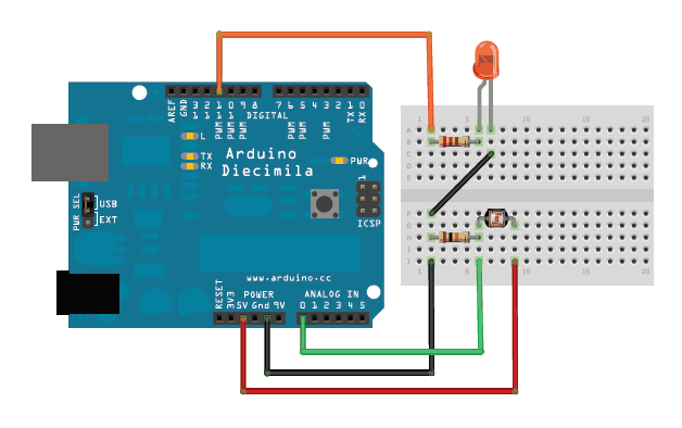
/*Photocell simple testing sketch.

Connect one end of the photocell to 5V, the other end to Analog 0.
Then connect one end of a 10K resistor from Analog 0 to ground
Connect LED from pin 9 through a resistor to ground
For more information see www.ladyada.net/learn/sensors/cds.html */

int photocellPin = 0; // the cell and 10K pulldown are connected to a0
int photocellReading; // the analog reading from the sensor divider
int LEDpin = 9; // connect Red LED to pin 09(PWM pin)
int LEDbrightness; //
void setup(void)
{
// We'll send debugging information via the Serial monitor
Serial.begin(9600);
}

void loop(void)
{
photocellReading = analogRead(photocellPin);

Serial.print("Analog reading = ");
Serial.println(photocellReading); // the raw analog reading

// LED gets brighter the darker it is at the sensor
// that means we have to -invert- the reading from 0-1023 back to 1023-0
photocellReading = 1023 - photocellReading;
//now we have to map 0-1023 to 0-255 since thats the range analogWrite uses
LEDbrightness = map(photocellReading, 0, 1023, 0, 255);
analogWrite(LEDpin, LEDbrightness);

delay(100);
}


LED Project - due 12 March 2010 - Fritz breadboard


I did a Fritz BreadBoard diagram,
but i could only make the BB view work.

The associated schematic was a real schemozzle, & every time i tried to fix it,
the wretched thing kept adding wires to my BB & i couldn't make them go away
without deleting the BB wires.. {siigh}.

As for the PCB view.. (duh!)

09 March 2010

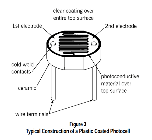
Task 24 - ladyada - CDS cell diagram


Here's a diagram of a cds (cadmium suphide) photocell

And this is the
ladyada sensors site.

Nice explanations - very clear, nice tidy site. Not full of visual pollution & other techno-riffraff


Task 23 - wikieducator.org


HowManyArduinos

Meh!!

Yes i looked.. couldn't understand a thing!!
Haven't got a blue's clue.. never bothered with wikis before.

Tried a few things to put an entry in - nothing made any sense..

08 March 2010

LED Project - due 12 March 2010 - software


/*
* Project: LED-Project_3-LED-blinks_12mar10
* Author: Jane-Maree Howard
* Date: Monday 08/03/2010
* Platform: Arduino 18
* Purpose: To demonstrate variable blink times for external 3-colour LED
* Operation: Sets up output pins (4 off) in setup() method;
* Declares pin definition variables (4 off)
* Defines loop() to perform various LED blinking & delay operations
* Here we use a 3-colour LED and first turn them all ON, then OFF.
* Then we successively blink the RED, GREEN & BLUE
* LEDs, each with the same delay time, which ramps
* from 10ms up to 200 millisec & back down again.
* Here we use two 'for-loops': one to ramp up the Delays, &
* the other to ramp them back down again
*/

int ledPin = 13; // on-board LED connected to digital pin 13
int redLedPin = 12; // RED LED connected to digital pin 12
int grnLedPin = 11; // GREEN LED connected to digital pin 11
int bluLedPin = 10; // BLUE LED connected to digital pin 10
// the variable delay is accomplished by..
int iMult; // ..the multiplier variable multiplied by..
int dLay = 10; // ..the delay variable, which is 10 milliseconds

// The setup() method runs once, when the sketch starts
void setup()
{
// initialize the 4 digital pins as outputs:
pinMode(ledPin, OUTPUT);
pinMode(redLedPin, OUTPUT); // Red LED output
pinMode(grnLedPin, OUTPUT); // Green LED output
pinMode(bluLedPin, OUTPUT); // Blue LED output
// turn on the on-board LED & wait 0.5 seconds
digitalWrite(ledPin, HIGH); // turn on-board LED on
delay(dLay*50); // delay 0.5 seconds (50 * 10ms)
}//end setup()

// Loop first turns all 3 LEDs on succesively, then turns them off again.
// Delay between each phase is about 100 milliseconds
// Loop now turns RED, GREEN & BLUE LEDs on & off cyclically
// with varying delay each time loop runs, &..
// ..repeats endlessly while Arduino has power

// At the half-way point the order of the LED-cycle is reversed;
// Viewers should try to spot this point! What indicates this?

void loop()
{
digitalWrite(redLedPin, HIGH); // turn red LED on
delay(50*dLay); // delay 500 milliseconds
digitalWrite(grnLedPin, HIGH); // turn green LED on
delay(50*dLay); // delay 500 milliseconds
digitalWrite(bluLedPin, HIGH); // turn blue LED on
delay(100*dLay); // delay 1 second
// Now turn them all off..
digitalWrite(redLedPin, LOW);
digitalWrite(grnLedPin, LOW);
digitalWrite(bluLedPin, LOW);
delay(50*dLay); // ..& wait 0.5 seconds

// Ramps delays UP - Red, Green & Blue LEDs each turn on, then off,
// with the delay time increasing with each for-loop cycle
// from 10 - 200 milliseconds
for (iMult=1; iMult<=20; iMult++ ) // now start 'increasing delay' for-loop { digitalWrite(redLedPin, HIGH); // turn red LED on.. delay(iMult*dLay); // ..delay 10millisec * multiplier.. digitalWrite(redLedPin, LOW); // ..turn red LED off &.. digitalWrite(grnLedPin, HIGH); // ..turn green LED on.. delay(iMult*dLay); // ..delay 10millisec * multiplier.. digitalWrite(grnLedPin, LOW); // ..turn green LED off &.. digitalWrite(bluLedPin, HIGH); // ..turn blue LED on.. delay(iMult*dLay); // ..delay 10millisec * multiplier.. digitalWrite(bluLedPin, LOW); // ..turn blue LED off delay(iMult*dLay); // ..delay 10millisec * multiplier. }//end for(iMult++) // Ramps delays DOWN again - Blue, Green & Red LEDs each turn on, then off, // with the delay time decreasing with each for-loop cycle // Note REVERSED ORDER now Blue-Green-Red for (iMult=20; iMult>=1; iMult-- ) // now start 'decreasing delay' for-loop
{
digitalWrite(bluLedPin, HIGH); // ..turn blue LED on..
delay(iMult*dLay); // ..delay 10millisec * multiplier..
digitalWrite(bluLedPin, LOW); // ..turn blue LED off
delay(iMult*dLay); // ..delay 10millisec * multiplier..
digitalWrite(grnLedPin, HIGH); // ..turn green LED on..
delay(iMult*dLay); // ..delay 10millisec * multiplier..
digitalWrite(grnLedPin, LOW); // ..turn green LED off &..
digitalWrite(redLedPin, HIGH); // ..turn red LED on..
delay(iMult*dLay); // ..delay 10millisec * multiplier..
digitalWrite(redLedPin, LOW); // ..turn red LED off &..
delay(iMult*dLay); // ..delay 10millisec * multiplier
}////end for(iMult--)

//..& repeat
}//end loop()


LED Project - due 12 March 2010

* In this project, i use a 3-colour LED
* and first turn them all ON, then OFF.
* Then i successively blink the RED, GREEN & BLUE
* LEDs, each with the same delay time, which ramps
* from 10ms up to 300 millisec & back down again.
* Here i use two 'for-loops': one to ramp up the Delays, &
* the other to ramp them back down again.

* Loop first turns all 3 LEDs on succesively,
* then turns them off again.
* Delay between each phase is about 100 milliseconds
* Loop now turns RED, GREEN & BLUE LEDs on & off
* cyclically with varying delay each time loop runs, &..
* ..repeats endlessly while Arduino has power.

* I hope (!!) to post a video of the project running (soon)

* At the half-way point the order of the LED-cycle is reversed;
* Viewers could try to spot this point!
* What indicates this?

Video

Task 22 - Alternate Red/Yellow LEDs blinking, writing "Red "/"Yellow " to Serial Monitor at each blink

/*
* Project: Blink2-task 22
* Author: Jane-Maree Howard
* Date: Monday 08/03/2010
* Platform: Arduino 18
* Purpose: To demonstrate blink time for two external LEDs,
* & writing to the Serial Monitor (SM)
* Operation: Sets up 2 output pins in setup() method;
* Declares 2 pin definition variables, for red & yellow LEDs;
* Sets up output to serial port & thus to SM
* Each differently-coloured LED blinks alternately,
* & the word "Red " or "Yellow " is written to the SM @ each blink..
* .. & repeat
*/

int ylwLedPin = 12; // yellow LED connected to digital pin 12
int redLedPin = 11; // red LED connected to digital pin 11
int dLay = 200; // delay variable

// The setup() method runs once, when the sketch starts
void setup()
{
//Now open the serial port..
Serial.begin(9600); // ..& set data transmission rate to SM at 9600Baud
// initialize digital pins 11 & 12 as outputs
pinMode(redLedPin, OUTPUT);
pinMode(ylwLedPin, OUTPUT);
}//end setup()

// Loop turns red LED (pin 11) on, prints the word "Red " to the SM,
// waits 200 milliseconds, turns red LED off,
// turns yellow LED on, prints the word "Yellow " to the SM,
// waits 200 milliseconds, turns yellow LED off, &..
// ..repeats endlessly while Arduino has power
void loop()
{
digitalWrite(redLedPin, HIGH); // turn red LED on
Serial.print("Red "); // print the word "Red " to SM
delay(200); // delay 200 milliseconds
digitalWrite(redLedPin, LOW); // then turn red LED off;
digitalWrite(ylwLedPin, HIGH); // turn yellow LED on,
Serial.print("Yellow "); // print the word "Yellow " to SM,
delay(200); // delay 200 milliseconds,
digitalWrite(ylwLedPin, LOW); // turn yellow LED off
}//end loop()


Task 21 - writing "Blink" to the Serial Monitor

/*
* Project: Blink2-task 21
* Author: Jane-Maree Howard
* Date: Monday 08/03/2010
* Platform: Arduino 18
* Purpose: To demonstrate blink time for external LED & writing to the Serial Monitor (SM)
* Operation: Sets up output pin in setup() method;
* Declares pin definition variable;
* Sets up output to serial port & thus to SM;
* The LED blinks & the word "Blink" is written to the SM @ each blink..
* & repeat
*/


int redLedPin = 11; // red LED connected to digital pin 11
int dLay = 1000; // delay variable

// The setup() method runs once, when the sketch starts
void setup()
{
//Now open the serial port..
Serial.begin(9600); // ..& set data transmission rate to SM at 9600Baud
// initialize digital pin 11 as output
pinMode(redLedPin, OUTPUT);
}//end setup()

// Loop turns red LED (pin 11) on, prints the word "Blink" to the SM,
// waits one second, turns red LED off, waits one second &..
// ..repeats endlessly while Arduino has power
void loop()
{
digitalWrite(redLedPin, HIGH); // turn red LED on
Serial.println("Blink"); // print to SM
delay(200); // delay 200 milliseconds
digitalWrite(redLedPin, LOW); // then turn red LED off
delay(200); // delay 200 milliseconds
}//end loop()


06 March 2010

Task 20 revised - ramping the LED rate UP then DOWN again

/*
* Project: Blink2-Task 20 revised
* Author: Jane-Maree Howard
* Date: Saturday 06/03/2010
* Platform: Arduino 18
* Purpose: To demonstrate variable blink times for external LEDs
* Operation: Sets up output pins (3 off) in setup() method;
* Declares pin definition variables (3 off)
* Defines loop() to perform various LED blinking & delay operations
* In this case, there is a varying blink rate of the Yellow LED,
* from 10ms up to 1 sec & back down again.
* Here we use two 'for-loops': one to ramp up the Delays, &
* the other to ramp them back down again
*/

int ledPin = 13; // on-board LED connected to digital pin 13
int ylwLedPin = 12; // yellow LED connected to digital pin 12
int redLedPin = 11; // red LED connected to digital pin 11
int dLay = 10; // delay variable - now 10 milliseconds

// The setup() method runs once, when the sketch starts
void setup()
{
// initialize the 3 digital pins as outputs:
pinMode(ledPin, OUTPUT);
pinMode(ylwLedPin, OUTPUT);
pinMode(redLedPin, OUTPUT);
// turn on the on-board LED & wait 4 seconds
digitalWrite(ledPin, HIGH); // turn on-board LED on
delay(dLay*400); // delay 4 seconds (400 * 10ms)
}//end setup()

// Loop turns yellow LED (pin12) off, red LED (pin 11) on, waits 2 seconds,
// turns red LED on (or off) & runs a 'for-loop' 100 times:
// turn yellow LED on & off, with varying delay each time loop runs, &..
// ..repeats endlessly while Arduino has power
void loop()
{
//Ramps delays UP - Red LED stays ON thru Yellow LED loop
digitalWrite(ylwLedPin, LOW); // turn yellow LED off
digitalWrite(redLedPin, HIGH); // turn red LED on & leave it ON
delay(200*dLay); // delay 2 seconds
for (int i=1; i<=100; i++ ) // now start 'YellowLED for-loop' { digitalWrite(ylwLedPin, HIGH); // NOW turn yellow LED on.. delay(i*dLay); // ..delay 10millisec * multiplier.. digitalWrite(ylwLedPin, LOW); // ..turn yellow LED off.. delay(i*dLay); // ..delay 10millisec * multiplier.. }//end for(i..) digitalWrite(redLedPin, LOW); // turn red LED off now //Ramps delays DOWN again - red LED blinks.. digitalWrite(ylwLedPin, LOW); // turn yellow LED off digitalWrite(redLedPin, HIGH); // turn red LED on delay(200*dLay); // delay 2 seconds digitalWrite(redLedPin, LOW); // First turn red LED off for (int i=100; i>1; i-- ) // now start 'YellowLED for-loop'
{
digitalWrite(ylwLedPin, HIGH); // NOW turn yellow LED on..
delay(i*dLay); // ..delay 10millisec * multiplier..
digitalWrite(ylwLedPin, LOW); // ..turn yellow LED off..
delay(i*dLay); // ..delay 10millisec * multiplier..
}//end for(i..)

//..& repeat
}//end loop()


I really do think this is closer to the mark..