29 March 2010
Embedded Notices, Chip8News & Sanguino
Embedded Notices 1-45
Chip8News
(just for my benefit)
And some more Chip-8 links..
More Chip8
CHIP-8 on Wikipedia
wikieducator Chip8
& this is Sanguino
Task 38 - button-activated photocell (LDR) numbered output to Serial Monitor.
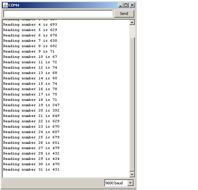
There's only a slight alteration to the software in Task 38.
Just means declaring a counter variable & incrementing it whenever the button is pushed & a reading is to be outputted.
You can see (readings 9-18) where i put my finger over the photocell, & later (27-31) where i just cupped the photocell in my hand..
/* check if the pushbutton is pressed.
if it is, the buttonState is HIGH, so..*/
if (buttonState == HIGH)
{
//..increment the reading counter &..
readNum++;
//..output the LDR reading to the SM
Serial.print("Reading number ");
Serial.print(readNum); // reading count
Serial.print(" is ");
Serial.println(photocellReading); // the raw analog reading
delay(100); // debounce delay
}// if..
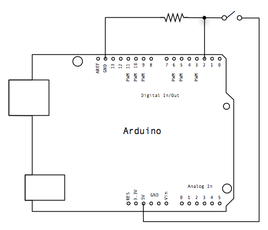
Task 38 - button-activated photocell (LDR) output to Serial Monitor. Breadboard.
This is the Fritzing breadboard circuit. Nothing complicated about it.
I do wish i could get the schematic to match the breadboard, but i still get a stupid tangle of unconnected components - very annoying!
 Fritzing breadboard circuit. Nothing complicated about it.
I do wish i could get the schematic to match the breadboard, but i still get a stupid tangle of unconnected components - very annoying!
Task 38 - button-activated photocell (LDR) output to Serial Monitor

The output "No output" shows the program is running. I won't bother next time; it's just for demo purposes..
When the button is pushed, the analog reading is sent to the Serial Monitor.
My reaction times aren't lightning fast, but even with a 'debounce' delay, it still gets a couple of readings out before my finger comes off the button.
Task 38 - button-activated photocell (LDR) output to Serial Monitor
/*
* Project: button_&_LDR_task_38
* Author: Jane-Maree Howard
* Date: Monday 29/03/2010
* Platform: Arduino 18
* Purpose: To send the reading from the LDR to the Serial Monitor
* whenever the button is pressed.
* The circuit:
* Connect one end of the photocell to 5V, the other end to Analog 0.
* Then connect one end of a 10K resistor from Analog 0 to ground
* Connect the pushbutton to pin 2 from +5V, &
* a 10K resistor attached from pin 2 to ground
*/
int buttonPin = 2; // the number of the pushbutton pin
int photocellPin = 0; // the cell and 10K pulldown are connected to a0
int photocellReading; // the analog reading from the sensor divider
int buttonState = 0; // variable for reading the pushbutton status
void setup()
{
/* We'll send the LDR state to the Serial monitor */
Serial.begin(9600); // baud rate 9600 should be set on the SM
// initialize the pushbutton pin 2 as an input:
pinMode(buttonPin, INPUT);
}//end setup()
void loop()
{
// read the state of the pushbutton value..
buttonState = digitalRead(buttonPin);
// read the value of the photocell
photocellReading = analogRead(photocellPin); //i.e. analog 0
/* check if the pushbutton is pressed.
if it is, the buttonState is HIGH, so..*/
if (buttonState == HIGH)
{
//..output the LDR reading to the SM
Serial.print("Analog reading = ");
Serial.println(photocellReading); // the raw analog reading
delay(100); // debounce delay
}// if..
else
{
Serial.println("No output");
}//..else
}//end loop()
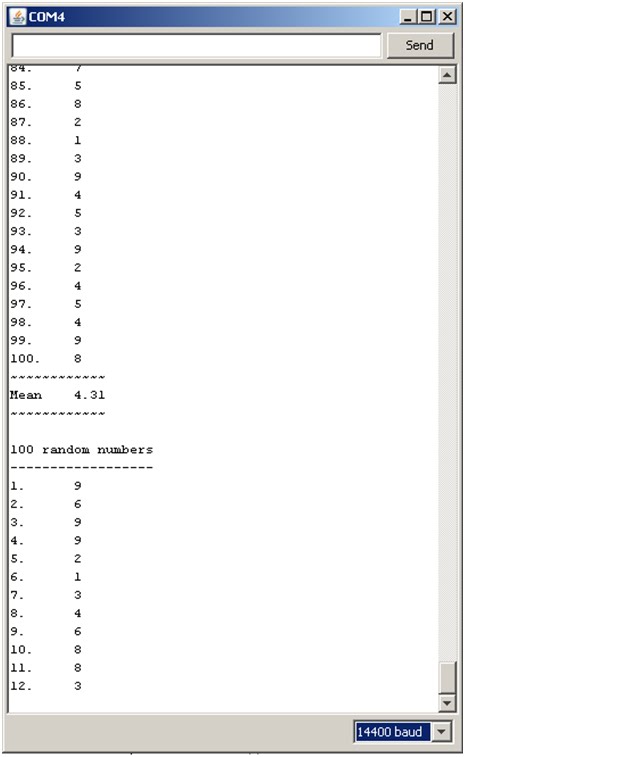
Task 37 - Random Number Program with high Baud rates

//set up random number seed & baud rate to SM
void setup()
{
//Serial.begin(300);
//Serial.begin(1200);
//Serial.begin(10126);
Serial.begin(10127);
//Serial.begin(280);
//Serial.begin(9600);
randomSeed(analogRead(0));
}//end setup()
The lower image records data @ 10126 Baud; above, @ 10127 Baud.
This may well be dependent on the computer i was using - i don't actually know, but on this one in D312, @ 10127 Baud the data turned to mush!
The SM's receiving rate was 14400 B, since its combo-box didn't allow for precise Baud rate matching..
Task 37 - Random Number Program with low Baud rates

//set up random number seed & baud rate to SM
void setup()
{
//Serial.begin(300);
//Serial.begin(1200);
//Serial.begin(10120);
//Serial.begin(12500);
Serial.begin(280);
//Serial.begin(9600);
randomSeed(analogRead(0));
}//end setup()
As you can see, i've put several different Baud rates into the program & commented them out one by one.
The lowest rate of coherent transmission was 290 Baud - the Serial Monitor has limited choices of Baud rate, but this was at 300B.
(280B - close but no cigar!)
26 March 2010
Task 28 - photocell-triggered LED switch: software
/*
* Project: Photocell_switch_task_28
* Author: Jane-Maree Howard
* Date: Friday 26/03/2010
* Platform: Arduino 18
* Purpose: To make a Photocell Switch for a LED.
* Operation: The circuit arrangement is the same as the ladyada
* LED dimmer, but this time the software has a trigger threshold
* for turning the LED on.
* The output of Analog 0 is measured as before, but instead
* of analogWrite() to the LED pin, digitalWrite is used to
* switch the LED on or off.
* We don't need to map the a0 output, since it's merely a trigger.
* Original description:
* Connect one end of the photocell to 5V, the other end to Analog 0.
Then connect one end of a 10K resistor from Analog 0 to ground
Connect LED from pin 9 through a resistor to ground
*/
int photocellPin = 0; // the cell and 10K pulldown are connected to a0
int photocellReading; // the analog reading from the sensor divider
int LEDpin = 9; // connect Red LED to pin 09(PWM pin)
int darkLevel = 100; // threshold for LED trigger action
void setup(void)
{
// We'll send debugging information via the Serial monitor
Serial.begin(9600); // baud rate 9600 should be set on the SM
digitalWrite(LEDpin, LOW);// turn LED off
}//end setup()
void loop(void)
{
digitalWrite(LEDpin, LOW);// turn LED off
photocellReading = analogRead(photocellPin); //i.e. analog 0
Serial.print("Analog reading = ");
Serial.print(photocellReading); // the raw analog reading
//we now use our 'darkLevel' variable to trigger the LED ON.
if (photocellReading <>
Task 28 - photocell-triggered LED switch: Serial Monitor output
As can be seen, it is fairly obvious from

the SM output when the trigger threshold is reached - i have
made the ON-message much more noticeable.
The actual threshold was set at 100, &
there's a reading of 105 just before the
reading of 80 that results in the LED turning on.
The only problem i see is my buffer resistor for the LED - it's too high, since the LED isn't very bright. That's probably due to the LED's duty cycle; it's mostly off, & stays on for only 0.5 sec, so it is rather dim..
..but it DOES work!
Task 41 - Registration for YABB


Here is confirmation of my registration for YABB.
My display name is:
kiwi-Jane-Maree
I have clicked on the validation URL & am now able to log in to YABB.
Well, no i wasn't actually - it didn't work & i only just found out today
25 March 2010
Task 36 - Generate 100 random numbers 0-9, calculate their Mean (average), & output the result to the Serial Monitor (2)

The Serial Monitor output shows the Mean calculated from the 100 random numbers generated by the program.
This variable must be a 'float' in order to show the result to (default) 2 decimal places; an 'int' or 'long' merely gives an integer - I found that this usually turned out to be 4, & occasionally 5 - unsatisfactory.
Task 36 - Generate 100 random numbers 0-9, calculate their Mean (average), & output the result to the Serial Monitor
/*
* Project: Random-numbers_task_36
* Author: Jane-Maree Howard
* Date: Thursday 25/03/2010
* Platform: Arduino 18
* Purpose: To generate 100 random numbers from 0-9 inclusive,
* label them 1-100 & output them to the
* Serial Monitor (SM), along with their average (mean)
*/
long randNumber; //random number to SM
float theMean; // will be the Mean of all 100 numbers
//set up random number seed & baud rate to SM
void setup()
{
Serial.begin(9600);
randomSeed(analogRead(0));
}//end setup()
//generates 100 random numbers 0-9 inclusive
void loop()
{
Serial.println("\n100 random numbers\n------------------");
delay(150);
theMean = 0; // initialise 'theMean'
for (int j=1; j<=100; j++) { randNumber = random(10); // random number from 0-9.. // ..& add to the total of the 100 numbers.. theMean = theMean + randNumber; Serial.print(j); Serial.print(".\t"); Serial.println(randNumber); delay(10); }//for (j++) //..now calculate the Mean (average) of the 100 random numbers.. theMean = theMean/100; Serial.print("~~~~~~~~~~~~\nMean\t"); //..& print it to the SM Serial.println(theMean); Serial.println("~~~~~~~~~~~~"); /* NOTE: theMean is a 'float'ing point number; using an 'int' or 'long' produces a rounding with no decimal places */ delay(500); //now repeat the cycle.. }//end loop()
HUMOUR - Wiley Miller's "Non Sequitur"
I'm a firm fan of this bloke
Wiley Miller's "Non Sequitur"
and while you're there you can find
other comics you may like..
..but "Non Sequitur" can be really really funny!
Wiley Miller's "Non Sequitur"
and while you're there you can find
other comics you may like..
..but "Non Sequitur" can be really really funny!
24 March 2010
Task 35 - 100 labelled random numbers between 0-9 on Serial Monitor
/*
* Project: Random-numbers_task_35
* Author: Jane-Maree Howard
* Date: Wednesday 24/03/2010
* Platform: Arduino 18
* Purpose: To generate 100 random numbers from 0-9 inclusive,
* label them 1-100 & output them to the
* Serial Monitor (SM)
*/
long randNumber; //random number to SM
//set up random number seed & baud rate to SM
void setup()
{
Serial.begin(9600);
randomSeed(analogRead(0));
}//end setup()
//generates 100 random numbers 0-9 inclusive
void loop()
{
Serial.println("\n100 random numbers");
delay(30);
for (int j=1; j<=100; j++) { randNumber = random(10); // random number from 0-9 Serial.print(j); Serial.print(".\t"); Serial.println(randNumber); delay(10); }//for (j++) delay(500); }//end loop()
Task 34 - 100 random numbers between 0-9 on Serial Monitor
/*
* Project: Random-numbers_task_34
* Author: Jane-Maree Howard
* Date: Wednesday 24/03/2010
* Platform: Arduino 18
* Purpose: To generate 100 random numbers from 0-9 inclusive,
* & output them to the Serial Monitor (SM)
*/
long randNumber; //random number to SM
//set up random number seed & baud rate to SM
void setup()
{
Serial.begin(9600);
randomSeed(analogRead(0));
}//end setup()
//generates 100 random numbers 0-9 inclusive
void loop()
{
Serial.println("\n100 random numbers");
for (int j=1; j<=100; j++)
{
randNumber = random(10); // random number from 0-9
Serial.println(randNumber);
delay(10);
}//for (j++)
delay(500);
}//end loop()
Motorised skateboard, & Jaycar
Just been down to Jaycar (electronics outfit opp. the Oval
& next to BP Everedi) - they've got heaps of stuff there..
AND i saw another (the same one - are there two?) motorised
skateboard - up close this time.
Powered by a little weed-whacker motor, it has two foot-
anchors on it & there is a joystick-thing but it has two cycle
hand-brakes - maybe that's how it's steered.
Then a bloke came out of Jaycar wearing a helmet & a backpack,
climbed onto this thing & went scooting up the road!!
YAY!!
23 March 2010
Arduino Key Words(3)
Each KEYWORD is a link to the
Arduino Reference page
map(value,fromLow,toLow,fromHigh,toHigh)
Arduino Reference page
map(value,fromLow,toLow,fromHigh,toHigh)
Description:Re-maps a number from one range to another.
That is, a value of fromLow would get mapped to toLow,
a value of fromHigh to toHigh,
values in-between to values in-between, etc.
Does not constrain values to within the range,
because out-of-range values are sometimes
intended and useful.
The constrain() function may be used
either before or after this function,
if limits to the ranges are desired.
Note that the "lower bounds" of either range may be
larger or smaller than the "upper bounds"
so the map() function may be used
to reverse a range of numbers,
for example
y = map(x, 1, 50, 50, 1);
The function also handles negative numbers well,
so that this example
y = map(x, 1, 50, 50, -100);
is also valid and works well.
The map() function uses integer math so will not generate fractions,
when the math might indicate that it should do so.
Fractional remainders are truncated,
and are not rounded or averaged.
Parameters
value: .......the number to map
fromLow: .the lower bound of the value's current range
fromHigh: the upper bound of the value's current range
toLow: ......the lower bound of the value's target range
toHigh: .....the upper bound of the value's target range
Returns:The mapped value.
Example
/* Map an analog value to 8 bits (0 to 255) */randomSeed(seed)
void setup() {}
void loop()
{
int val = analogRead(0);
val = map(val, 0, 1023, 0, 255);
analogWrite(9, val);
}
Description
randomSeed() initializes the pseudo-random number generator,
causing it to start at an arbitrary point in its random sequence.
This sequence, while very long, and random, is always the same.
If it is important for a sequence of values
generated by random() to differ,
on subsequent executions of a sketch,
use randomSeed() to initialize the random number generator
with a fairly random input,
such as analogRead() on an unconnected pin.
Conversely, it can occasionally be useful to use
pseudo-random sequences that repeat exactly.
This can be accomplished by calling randomSeed()
with a fixed number, before starting the random sequence.
Parameters: long, int - pass a number to generate the seed.
long randNumber;

void setup(){
Serial.begin(9600);
randomSeed(analogRead(0));
}

void loop(){
randNumber = random(300);
Serial.println(randNumber);

delay(50);
}
Task29 - wikieducator.org (3)
And this is Arduino Resources
Here's the Help Page for making a wiki book.
Hopefully (she says) i can figure out how to do this stuff,
and that will be Something else i know how to do..
i'm catching up (slowly!) with this Online Generation lot..
Here's the Help Page for making a wiki book.
Hopefully (she says) i can figure out how to do this stuff,
and that will be Something else i know how to do..
i'm catching up (slowly!) with this Online Generation lot..
Task 33 - Arduino Key Words(2)
Each KEYWORD is a link to the
Arduino Reference page
pinMode()
digitalRead()
Arduino Reference page
pinMode()
Description
Configures the specified pin to behave either as an input or an output.
See the description of digital pins for details.
Syntax
pinMode(pin, mode)
Parameters
pin: the number of the pin whose mode you wish to set
int ledPin = 13;                 // LED connected to digital pin 13

void setup()
{
pinMode(ledPin, OUTPUT);      // sets the digital pin as output
}

void loop()
{
digitalWrite(ledPin, HIGH);   // sets the LED on
delay(1000);                  // waits for a second
digitalWrite(ledPin, LOW);    // sets the LED off
delay(1000);                  // waits for a second
}
digitalRead()
Description
Reads the value from a specified digital pin, either HIGH or LOW.
Syntax
digitalRead(pin)
Parameters
pin: the number of the digital pin you want to read (int)
Returns
int ledPin = 13; // LED connected to digital pin 13
int inPin = 7;   // pushbutton connected to digital pin 7
int val = 0;     // variable to store the read value

void setup()
{
pinMode(ledPin, OUTPUT);      // sets the digital pin 13 as output
pinMode(inPin, INPUT);      // sets the digital pin 7 as input
}

void loop()
{
val = digitalRead(inPin);   // read the input pin
digitalWrite(ledPin, val);    // sets the LED to the button's value
}
Embedded Notices & Chip8News
Embedded Notices 1-45
Chip8News
(just for my benefit)
And some more Chip-8 links..
More Chip8
CHIP-8 on Wikipedia
wikieducator Chip8
i did Start>Run [cmd] >OK to get a command-line window..
On intellectual property rights & patent law
From Newswise comes this article entitled:
Naturally, the Free Software Foundation & other groups advocating open source standards will be buoyed up by support from such luminaries, but of course you can expect reaction from the vested-interest & quasi-monopoly sectors..
Economists Say Copyright and Patent Laws Are Killing Innovation; Hurting Economy
It's an interesting idea, especially when you consider the assertion that software is dragging the chain vis-a-vis hardware innovation.Naturally, the Free Software Foundation & other groups advocating open source standards will be buoyed up by support from such luminaries, but of course you can expect reaction from the vested-interest & quasi-monopoly sectors..
22 March 2010
Task 32 - outputting the button result to the SM
/*
* Project: button_task_32
* Author: Jane-Maree Howard
* Date: Monday 22/03/2010
* Platform: Arduino 18
* Purpose: To send the result of the 'button' operation.
* to the Serial Monitor
Turns on and off a light emitting diode(LED) connected to digital
pin 13, when pressing a pushbutton attached to pin 2.
The circuit:
* LED attached from pin 13 to ground
* pushbutton attached to pin 2 from +5V
* 10K resistor attached to pin 2 from ground
* Note: on most Arduinos there is already an LED
on the board attached to pin 13.
created 2005
by DojoDave
modified 17 Jun 2009
by Tom Igoe
This example code is in the public domain.
http://www.arduino.cc/en/Tutorial/Button
*/
/* Constants won't change.
They're used here to set pin numbers:*/
const int buttonPin = 2; // the number of the pushbutton pin
const int ledPin = 13; // the number of the LED pin
// Variables will change:
int buttonState = 0; // variable for reading the pushbutton status
void setup()
{
// initialize the LED pin 13 as an output:
pinMode(ledPin, OUTPUT);
// initialize the pushbutton pin 2 as an input:
pinMode(buttonPin, INPUT);
/* We'll send the button state & the LED state
to the Serial monitor */
Serial.begin(9600); // baud rate 9600 should be set on the SM
}//end setup()
void loop()
{
// read the state of the pushbutton value:
buttonState = digitalRead(buttonPin);
// check if the pushbutton is pressed.
// if it is, the buttonState is HIGH:
if (buttonState == HIGH)
{
// turn LED on:
digitalWrite(ledPin, HIGH);
Serial.println("Button pressed - LED on");
}// if..
else
{
// turn LED off:
digitalWrite(ledPin, LOW);
Serial.println("--LED off");
}//..else..
}//end loop()
Task 32 - outputting the 'button' program to the Serial Monitor
 It's a bit small, but the output is fairly clear - the words "Button pressed - LED on" are easily distinguished from "--LED off"
Task 31 - reversing the button operation via software
/*
/*
* Project: button_task_31
* Author: Jane-Maree Howard
* Date: Monday 22/03/2010
* Platform: Arduino 18
* Purpose: To reverse the order of the 'button' operation.
Turns on and off a light emitting diode(LED) connected to digital
pin 13, when pressing a pushbutton attached to pin 2.
The circuit:
* LED attached from pin 13 to ground
* pushbutton attached to pin 2 from +5V
* 10K resistor attached to pin 2 from ground
* Note: on most Arduinos there is already an LED
on the board attached to pin 13.
created 2005
by DojoDave
modified 17 Jun 2009
by Tom Igoe
This example code is in the public domain.
http://www.arduino.cc/en/Tutorial/Button
*/
/* Constants won't change.
They're used here to set pin numbers:*/
const int buttonPin = 2; // the number of the pushbutton pin
const int ledPin = 13; // the number of the LED pin
// Variables will change:
int buttonState = 0; // variable for reading the pushbutton status
void setup()
{
// initialize the LED pin 13 as an output:
pinMode(ledPin, OUTPUT);
// initialize the pushbutton pin 2 as an input:
pinMode(buttonPin, INPUT);
}//end setup()
void loop()
{
// read the state of the pushbutton value:
buttonState = digitalRead(buttonPin);
// check if the pushbutton is pressed.
// if it is, the buttonState is HIGH:
if (buttonState == HIGH)
{
// turn LED off:
digitalWrite(ledPin, LOW);
}// if..
else
{
// turn LED on:
digitalWrite(ledPin, HIGH);
}//..else..
}//end loop()
Task 30 - using the button. Schematic.
 The circuit is quite simple - pin 2 is pulled down to 0V through the 10k pull-down resistor, until the button is closed. This pulls pin 2 up to +5V, & this causes pin 13 to go HIGH & light up the on-board LED.
The actual push-button has 4 terminals, but they are paired, (as is evident on the breadboard).
Task 30 - using the button
/*
Button
Turns on and off a light emitting diode(LED) connected to digital
pin 13, when pressing a pushbutton attached to pin 7.
The circuit:
* LED attached from pin 13 to ground
* pushbutton attached to pin 2 from +5V
* 10K resistor attached to pin 2 from ground
* Note: on most Arduinos there is already an LED on the board
attached to pin 13.
created 2005
by DojoDave
modified 17 Jun 2009
by Tom Igoe
This example code is in the public domain.
http://www.arduino.cc/en/Tutorial/Button
*/
// constants won't change. They're used here to
// set pin numbers:
const int buttonPin = 2; // the number of the pushbutton pin
const int ledPin = 13; // the number of the LED pin
// variables will change:
int buttonState = 0; // variable for reading the pushbutton status
void setup() {
// initialize the LED pin as an output:
pinMode(ledPin, OUTPUT);
// initialize the pushbutton pin as an input:
pinMode(buttonPin, INPUT);
}
void loop(){
// read the state of the pushbutton value:
buttonState = digitalRead(buttonPin);
// check if the pushbutton is pressed.
// if it is, the buttonState is HIGH:
if (buttonState == HIGH) {
// turn LED on:
digitalWrite(ledPin, HIGH);
}
else {
// turn LED off:
digitalWrite(ledPin, LOW);
}
}
Task 27 - ladyada software improved
/*
* Project: ladyada_Photocell_task_27
* Author: Jane-Maree Howard
* Date: Monday 22/03/2010
* Platform: Arduino 18
* Purpose: To improve on the ladyada Photocell operation.
* Operation: The previous arrangement showed good sensitivity on the
* Serial monitor, but very little on the LED.
* NOTE: I took out the line
* photocellReading = 1023 - photocellReading;
* and it started to behave as I thought it should i.e.
* getting darker as the photocell was darkened & v.v.
* Original description:
* Connect one end of the photocell to 5V, the other end to Analog 0.
Then connect one end of a 10K resistor from Analog 0 to ground
Connect LED from pin 9 through a resistor to ground
For more information see www.ladyada.net/learn/sensors/cds.html
*/
int photocellPin = 0; // the cell and 10K pulldown are connected to a0
int photocellReading; // the analog reading from the sensor divider
int LEDpin = 9; // connect Red LED to pin 09(PWM pin)
int LEDbrightness; //
void setup(void)
{
// We'll send debugging information via the Serial monitor
Serial.begin(9600); // baud rate 9600 should be set on the SM
}//end setup()
void loop(void)
{
photocellReading = analogRead(photocellPin); //i.e. analog 0
Serial.print("Analog reading = ");
Serial.println(photocellReading); // the raw analog reading
//now we have to map 0-1023 to 0-255 since thats the range analogWrite uses
LEDbrightness = map(photocellReading, 0, 1023, 0, 255);
analogWrite(LEDpin, LEDbrightness);
delay(100);
}//end loop()
/* The device now behaves as it should- getting brighter or darker with the cds Photocell's light level.
Definitely an improvement!!*/
Morse Code flasher & buzzer - Breadboard Fritz

I did a Fritz breadboard of the Morse Code buzzer - there's nothing complicated about it, just rather messy with all the wires..
A breadboard shield would be nice (so i ought to get on & make one!).
Using Arduino software - user-defined functions (4) - a Morse Code flasher & buzzer
/*
* Project: functions_MorseCodeBuzzer
* Author: Jane-Maree Howard
* Date: Monday 22/03/2010
* Platform: Arduino 18
* Purpose: To demonstrate a Morse code buzzer.
* Operation: The buzzer makes only clicking noises so
* evidently we will have to make it oscillate,
* i.e. buzz. This will need its own routine call.
* I expect turning it on-off repeatedly will be enough.
* Most of the code has been re-used from MorseCode_MyName,
* since it does much the same thing, but with the exception
* of a buzzer routine call for every LED flash, since this
* what is associated with the sound.
*/
int pinBlu = 10; // off-board Blue LED
int pinBuzz = 12; // output to buzzer
int iBuzz = 12; // 'Buzz' oscillations cycle count
int i; // 'Buzz' oscillations counter
int dLay = iBuzz*3; // basic delay = 'dot' buzz cycle
void setup()
{
pinMode(pinBlu, OUTPUT);
pinMode(pinBuzz, OUTPUT);
digitalWrite(pinBlu, LOW);
digitalWrite(pinBuzz, LOW);
}//end setup()
/* This loop makes use of user-defined functions called dot() and dash()
which in turn make up the Morse letters e.g. Juliet()
Here I spell out my name: 'Jane-Maree Paula Howard'
*/
void loop()
{
delay(7*dLay); // 1.75 sec delay - delay between words
delay(7*dLay); // 1.75 sec delay - delay between words
delay(7*dLay); // 1.75 sec delay - delay between words
Juliet(); //J
Alpha(); //A
November(); //N
Echo(); //E
Hyphen(); //-
Mike(); //M
Alpha(); //A
Romeo(); //R
Echo(); //E
Echo(); //E
delay(7*dLay); // 1.75 sec delay - delay between words
Papa(); //P
Alpha(); //A
Uniform(); //U
Lima(); //L
Alpha(); //A
delay(7*dLay); // 1.75 sec delay - delay between words
Hotel(); //H
Oscar(); //O
Whiskey(); //W
Alpha(); //A
Romeo(); //R
Delta(); //D
delay(7*dLay); // 1.75 sec delay - delay between words
}//end loop() // Main body of program
/* Now we define the functions buzz(), dot() & dash()
These represent the 'character elements' of each alpha-numeric character.
Then we define the Alpha characters in terms of dot() & dash()
Note that buzz() is included in dot() & dash()
As can be seen above, calling these functions is quite easy.
*/
// buzz() is actually an oscillation routine; frequency ~500Hz
void buzz(int j)
{
for (i=0; i
{
delay(2);
digitalWrite(pinBuzz, HIGH);
delay(1);
digitalWrite(pinBuzz, LOW);
}//for(++)
}//end buzz()
void dot()
{
digitalWrite(pinBlu, HIGH);
buzz(iBuzz);
//delay(dLay); // 250 millisec delay - length of 'character element'
digitalWrite(pinBlu, LOW);
delay(2*dLay); // 500 millisec delay - delay between 'character elements'
}//end dot()
void dash()
{
digitalWrite(pinBlu, HIGH);
buzz(iBuzz*3);
//delay(dLay*3); // 750 millisec delay - length of 'character element'
digitalWrite(pinBlu, LOW);
delay(2*dLay); // 500 millisec delay - delay between 'character elements'
}//end dash()
/* Now we make functions using functions: in this case the Morse alphabet of
various characters; named using the military alpha-word-code - Alpha Bravo etc
*/
//Juliet di-dah-dah-dah
void Juliet()
{
dot();
dash();
dash();
dash();
delay(2*dLay);
}//end juliet()
//Alpha di-dah
void Alpha()
{
dot();
dash();
delay(2*dLay);
}//end Alpha()
//November dah-dit
void November()
{
dash();
dot();
delay(2*dLay);
}//end November()
//Echo dit
void Echo()
{
dot();
delay(2*dLay);
}//end Echo()
//Mike dah-dah
void Mike()
{
dash();
dash();
delay(2*dLay);
}//end Mike()
//Romeo di-dah-dit
void Romeo()
{
dot();
dash();
dot();
delay(2*dLay);
}//end Romeo()
//Hyphen dah-di-di-di-di-dah
void Hyphen()
{
dash();
dot();
dot();
dot();
dot();
dash();
delay(2*dLay);
}//end Hyphen()
//Papa di-dah-dah-dit
void Papa()
{
dot();
dash();
dash();
dot();
delay(2*dLay);
}//end Papa()
//Uniform di-di-dah
void Uniform()
{
dot();
dot();
dash();
delay(2*dLay);
}//end Uniform()
//Lima di-dah-di-dit
void Lima()
{
dot();
dash();
dot();
dot();
delay(2*dLay);
}//end Lima()
//Hotel di-di-di-dit
void Hotel()
{
dot();
dot();
dot();
dot();
delay(2*dLay);
}//end Hotel()
//Oscar dah-dah-dah
void Oscar()
{
dash();
dash();
dash();
delay(2*dLay);
}//end Oscar()
//Whiskey dah-dah-dah
void Whiskey()
{
dot();
dash();
dash();
delay(2*dLay);
}//end Whiskey()
//Delta dah-dit
void Delta()
{
dash();
dot();
dot();
delay(2*dLay);
}//end Delta()
/* end of user-defined functions */
20 March 2010
LED PROJECT software revisited using functions(2)
Adding the code:
void onFor50(int lPin)
{
digitalWrite(lPin, HIGH); // turn LED on
delay(50*dLay); // delay 500 milliseconds
}// onFor50()
& replacing with e.g. onFor50(bluLedPin);
got the code down to 1382 bytes, another 20 bytes less
Tasks {si-i-igh} - yes i'll get around to them..
Been mucking about with functions, which i think is important, since it's going to save a lot of coding time & space. I'm thinking also of building a little breadboard to make construction just a little simpler - fewer straggly wires (which keep falling out, & getting tangled up with other stuff).
If i take a little time to build this thing, i might save more time later on..
LED PROJECT software revisited using functions
/*
* Project: LED-Project_3-LED-blinks_revisited
* Author: Jane-Maree Howard
* Date: Saturday 20/03/2010
* Platform: Arduino 18
* Purpose: To demonstrate variable blink times for external 3-colour LED
* Operation: Sets up output pins (4 off) in setup() method;
* Declares pin definition variables (4 off)
* Defines loop() to perform various LED blinking & delay operations
* Here we use a 3-colour LED and first turn them all ON, then OFF.
* Then we successively blink the RED, GREEN & BLUE
* LEDs, each with the same delay time, which ramps
* from 10ms up to 250 millisec & back down again.
* Here we use two 'for-loops': one to ramp up the Delays, &
* the other to ramp them back down again.
* This revisited version uses a function with an integer parameter
*/
int ledPin = 13; // on-board LED connected to digital pin 13
int redLedPin = 12; // RED LED connected to digital pin 12
int grnLedPin = 11; // GREEN LED connected to digital pin 11
int bluLedPin = 10; // BLUE LED connected to digital pin 10
// the variable delay is accomplished by..
int iMult; // ..the multiplier variable multiplied by..
int dLay = 10; // ..the delay variable, which is 10 milliseconds
// The setup() method runs once, when the sketch starts
void setup()
{
// initialize the 3 digital pins as outputs:
pinMode(ledPin, OUTPUT);
pinMode(redLedPin, OUTPUT); // Red LED output
pinMode(grnLedPin, OUTPUT); // Green LED output
pinMode(bluLedPin, OUTPUT); // Blue LED output
// turn on the on-board LED & wait 0.5 seconds
digitalWrite(ledPin, HIGH); // turn on-board LED on
delay(dLay*50); // delay 0.5 seconds (50 * 10ms)
}//end setup()
/* Loop first turns all 3 LEDs on succesively, then turns them off again.
Delay between each phase is about 100 milliseconds
Loop now turns RED, GREEN & BLUE LEDs on & off cyclically
with varying delay each time loop runs, &..
..repeats endlessly while Arduino has power
At the half-way point the order of the LED-cycle is reversed;
Viewers should try to spot this point! What indicates this?
*/
void loop()
{
digitalWrite(redLedPin, HIGH); // turn red LED on
delay(50*dLay); // delay 500 milliseconds
digitalWrite(grnLedPin, HIGH); // turn green LED on
delay(50*dLay); // delay 500 milliseconds
digitalWrite(bluLedPin, HIGH); // turn blue LED on
delay(100*dLay); // delay 1 second
// Now turn them all off..
digitalWrite(redLedPin, LOW);
digitalWrite(grnLedPin, LOW);
digitalWrite(bluLedPin, LOW);
delay(50*dLay); // ..& wait 0.5 seconds
// Ramps delays UP - Red, Green & Blue LEDs each turn on, then off,
// with the delay time increasing with each for-loop cycle
// from 10 - 200 milliseconds
for (iMult=1; iMult<=20; iMult++ ) // now start 'increasing delay' for-loop
{
flash(redLedPin); // flash red LED..
flash(grnLedPin); // flash green LED...
flash(bluLedPin); // flash blue LED...
}//end for(iMult++)
// Ramps delays DOWN again - Blue, Green & Red LEDs each turn on, then off,
// with the delay time decreasing with each for-loop cycle
// Note REVERSED ORDER now Blue-Green-Red
for (iMult=20; iMult>=1; iMult-- ) // now start 'increasing delay' for-loop
{
flash(bluLedPin); // flash blue LED..
flash(grnLedPin); // flash green LED...
flash(redLedPin); // flash red LED...
}////end for(iMult--)
//..& repeat
}//end loop()
/* Now we define a function to take care of the more repetitious bits of code,
in this case, turning variously-coloured LEDs on & off
*/
void flash(int lPin) // lPin is the parameter for, e.g. bluLedPin,
i.e. the BLUE LED
{
digitalWrite(lPin, HIGH); // ..turn LED on..
delay(iMult*dLay); // ..delay 10millisec * multiplier..
digitalWrite(lPin, LOW); // ..turn LED off..
delay(iMult*dLay); // ..delay 10millisec * multiplier..
}//end flash()
This code consumes 1402 bytes, as against 1726 for the 'old' version.
That's a saving of ~19%! Important in such a small device as Arduino..
Using Arduino software - user-defined functions (3)
/*
* Project: functions_Morse Code - MyName
* Author: Jane-Maree Howard
* Date: Saturday 20/03/2010
* Platform: Arduino 18
* Purpose: (1)To demonstrate a sketch for flashing Morse code
(2)This document explains how to create a library for Arduino.
* Operation: It starts with a sketch and explains how to convert its functions into a library.
* This allows other people to easily use the code that you've written
* and to easily update it as you improve the library.
* We start with a sketch that does simple Morse code:
* The code is simple & ideal for telegraphy: a sequence of 'dots' & 'dashes'
* (or 'dit' & 'dah') encoding alpha-numeric characters,
* beginning with 'e'='dit', & 't'='dah' (the most commonly used letters in
* English text, & progressing to the less common characters.
* Wikipedia gives the 'mark-space' intervals for Morse code as follows:
* 1/ A 'dash' is equal to 3 'dots'
* 2/ The space between parts of the same letter is equal to 1 'dot'
* 3/ The space between two letters is equal to 3 'dots'
* 4/ The space between two words is equal to 7 'dots'
* Here I spell out my name: Jane-Maree, using two levels of function call
*/
int pin = 13; //on-board LED
int dLay = 250; //basic delay
void setup()
{
pinMode(pin, OUTPUT);
}//end setup()
/* This loop makes use of user-defined functions called dot() and dash()
which in turn make up the Morse letters e.g. Juliet()
Here I spell out my name: 'Jane-Maree'
*/
void loop()
{
Juliet(); //J
Alpha(); //A
November(); //N
Echo(); //E
Hyphen(); //-
Mike(); //M
Alpha(); //A
Romeo(); //R
Echo(); //E
Echo(); //E
delay(7*dLay); // 1.75 sec delay - delay between words
delay(7*dLay); // 1.75 sec delay - delay between words
}//end loop() // Main body of program
/* Now we define the functions dot() & dash()
These represent the 'character elements' of each alpha-numeric character
As can be seen above, calling these functions is quite easy */
void dot()
{
digitalWrite(pin, HIGH);
delay(dLay); // 250 millisec delay - length of 'character element'
digitalWrite(pin, LOW);
delay(2*dLay); // 500 millisec delay - delay between 'character elements'
}//end dot()
void dash()
{
digitalWrite(pin, HIGH);
delay(dLay*3); // 750 millisec delay - length of 'character element'
digitalWrite(pin, LOW);
delay(2*dLay); // 500 millisec delay - delay between 'character elements'
}//end dash()
/* Now we make functions using functions: in this case the Morse alphabet of
various characters; named using the military alpha-word-code - Alpha Bravo etc
*/
//Juliet di-dah-dah-dah
void Juliet()
{
dot();
dash();
dash();
dash();
delay(2*dLay);
}//end juliet()
//Alpha di-dah
void Alpha()
{
dot();
dash();
delay(2*dLay);
}//end Alpha()
//November dah-dit
void November()
{
dash();
dot();
delay(2*dLay);
}//end November()
//Echo dit
void Echo()
{
dot();
delay(2*dLay);
}//end Echo()
//Mike dah-dah
void Mike()
{
dash();
dash();
delay(2*dLay);
}//end Mike()
//Romeo di-dah-dit
void Romeo()
{
dot();
dash();
dot();
delay(2*dLay);
}//end Romeo()
//Hyphen dah-di-di-di-di-dah
void Hyphen()
{
dash();
dot();
dot();
dot();
dot();
dash();
delay(2*dLay);
}//end Hyphen()
/* end of user-defined functions */
18 March 2010
Using Arduino software - user-defined functions (2)
And here it is - passing PARAMETERS to a FUNCTION.
Example
To "call" our simple multiply function, we pass it parameters of the datatype that it is expecting:
This is taken directly from the tutorial called 'Arduino - FunctionDeclaration'
Using Arduino software - user-defined functions
This little program is found in the tutorial on FUNCTIONS.
I've titivated it up a bit
/*
* Project: functions_Morse Code - SOS
* Author: Jane-Maree Howard
* Date: Thursday 18/03/2010
* Platform: Arduino 18
* Purpose: (1)To demonstrate a sketch for flashing Morse code
(2)This document explains how to create a library for Arduino.
* Operation: It starts with a sketch and explains how to convert its functions into a library.
* This allows other people to easily use the code that you've written
* and to easily update it as you improve the library.
* We start with a sketch that does simple Morse code:
* Invented by Samuel Morse (back in the day!), this telegraph code was later used for
* wireless (radio) telegraphy in conditions where radio-telephony (speech) was unclear
* owing to weak signals, radio-interference etc. An operator with a good 'fist' could
* transmit 40-50 words per minute (or possibly more). The code is simple & ideal for
* telegraphy: a sequence of 'dots' & 'dashes' (or 'dit' & 'dah') encoding alpha-numeric
* characters, beginning with 'e'='dit', & 't'='dah' (the most commonly used letters in
* English text), & progressing to the less common characters.
* Here 'dit-dit-dit dah-dah-dah dit-dit-dit' encodes the international distress call 'SOS'
*/
int pin = 13; //on-board LED
int dLay = 250; //basic delay
void setup()
{
pinMode(pin, OUTPUT);
}//end setup()
/* This loop makes use of user-defined functions called dot() and dash() */
void loop()
{
dot(); dot(); dot(); // Morse code: . . . = S
delay(2*dLay); // delay between characters
dash(); dash(); dash(); // Morse code: - - - = O
delay(2*dLay);
dot(); dot(); dot(); // Morse code: . . . = S
delay(2*dLay);
delay(12*dLay); // 3 seconds
}//end loop() // Main body of program
/* Now we define the functions dot() & dash()
These represent the 'character elements' of each alpha-numeric character
As can be seen above, calling these functions is quite easy */
void dot()
{
digitalWrite(pin, HIGH);
delay(dLay); // 250 millisec delay - length of 'character element'
digitalWrite(pin, LOW);
delay(dLay); // 250 millisec delay - delay between 'character elements'
}//end dot()
void dash()
{
digitalWrite(pin, HIGH);
delay(dLay*4); // 1 second delay - length of 'character element'
digitalWrite(pin, LOW);
delay(dLay); // 250 millisec delay - delay between 'character elements'
}//end dash()
/* end of user-defined functions */
This is taken directly (with my own additions) from 'Arduino - LibraryTutorial'
16 March 2010
Motorised skateboard/scooter
About tea-time last night (Monday) i saw a bloke whizzing up Dundas St on what looked like motorised skateboard!
Made a whining sound so it seems to have been electrically powered..
But it had a joystick arrangement (more like a scooter really).. & pram-wheels by the looks of it, not underneath as on a skateboard.
Wonder what could be done with an Arduino-based control system?
Sometimes s-board riders need to be able to 'side-step'-steer - an arrangement not unlike that on the Honda Prelude 4-wheel steering: below about 35km/hr the rear wheels point away from the front wheels, progressively decreasing the amount of 'steer' until above 35 km/hr they start to point in the same direction as the front wheels - a 'side-step' as opposed to a 'twirl' (if that makes sense)..
15 March 2010
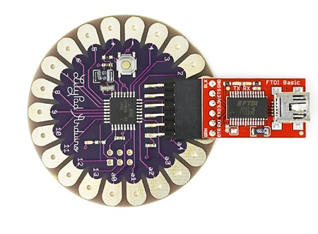
Task 23 - wikieducator.org(2) - LilyPad Arduino
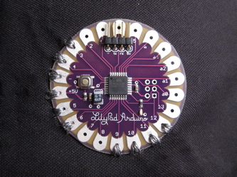
 The LilyPad Arduino (see below).
You can actually sew this onto a garment using the holes arranged round the edge.
You could put a nicely-designed shield on top of the LilyPad & make it do all kinds of cool things :-)
Do be careful, though, it's rather more fragile than other Arduinos, so if you accidentally reverse polarity, or connect more than 5.5v to the + terminal you're going to kill the Mega, & that means a new LilyPad!!
The little red board
is the
SparkFun FTDI Basic Breakout
for programming the LilyPad..
14 March 2010
Task 25 - Arduino Key Words(1)
Each KEYWORD is a link to the
Arduino Reference page
setup()
--the first of the two main parts of any Arduino program.
--determines the state of the digital pins 2-13 i.e. OUPUT
--or INPUT. Also the data rate to the Serial Monitor needs
--to be set here. Example:
setup()
{
pinMode (13, OUTPUT); //pin 13 set as output
Serial.begin(9600); //data rate to SM is 9600 baud
}
loop()
--the second of the two main parts to any Arduino program.
--this is where the working part of the program is written.
--any functions called within loop() are written AFTER the
--loop() part of the program
--Any code here is endlessly repeated as long as there is power
--to the Arduino board to which it is uploaded
analogRead()
Serial.print()
Description: Prints data to the serial port as human-readable ASCII text.
his command can take many forms.
Numbers are printed using an ASCII character for each digit.
Floats are similarly printed as ASCII digits, defaulting to two decimal places. Bytes are sent as a single character.
Characters and strings are sent as is.
Syntax
Arduino Reference page
setup()
--the first of the two main parts of any Arduino program.
--determines the state of the digital pins 2-13 i.e. OUPUT
--or INPUT. Also the data rate to the Serial Monitor needs
--to be set here. Example:
setup()
{
pinMode (13, OUTPUT); //pin 13 set as output
Serial.begin(9600); //data rate to SM is 9600 baud
}
loop()
--the second of the two main parts to any Arduino program.
--this is where the working part of the program is written.
--any functions called within loop() are written AFTER the
--loop() part of the program
--Any code here is endlessly repeated as long as there is power
--to the Arduino board to which it is uploaded
// loop checks the button pin each time,
// and will send serial if it is pressed
void loop()
{
  if (digitalRead(buttonPin) == HIGH)
    serialWrite('H');
  else
    serialWrite('L');

  delay(1000);
}
analogRead()
Description
Reads the value from the specified analog pin.
The ArduinoMega board contains a 16 channel 10-bit analog to digital converter.
This means that it will map input voltages between 0 and 5 volts
into integer values between 0 and 1023.
This yields a resolution between readings of: 5 volts / 1024 units or,
0.0049 volts (4.9 mV) per unit.
The input range and resolution can be changed using analogReference().
It takes about 100 microseconds (0.0001 s) to read an analog input,
so the maximum reading rate is about 10,000 times a second.
int analogPin = 3;     // potentiometer wiper (middle terminal) connected to analog pin 3
            // outside leads to ground and +5V
int val = 0;           // variable to store the value read

void setup()
{
Serial.begin(9600);          //  setup serial
}

void loop()
{
val = analogRead(analogPin);    // read the input pin
Serial.println(val);             // debug value
}
Serial.print()
Description: Prints data to the serial port as human-readable ASCII text.
his command can take many forms.
Numbers are printed using an ASCII character for each digit.
Floats are similarly printed as ASCII digits, defaulting to two decimal places. Bytes are sent as a single character.
Characters and strings are sent as is.
Syntax
Serial.print(val)
Serial.print(val, format)
Parameters
val: the value to print - any data type
/*Uses a FOR loop for data and prints a number in various formats.
*/
int x = 0; // variable
void setup() {
Serial.begin(9600); // open the serial port at 9600 bps:
}
void loop() {
// print labels
Serial.print("NO FORMAT"); // prints a label
Serial.print("\t"); // prints a tab
Serial.print("DEC");
Serial.print("\t");
Serial.print("HEX");
Serial.print("\t");
for(x=0; x< style="font-weight: bold;">
Serial.println()Description
Prints data to the serial port as human-readable ASCII text
followed by a carriage return character (ASCII 13, or '\r')
and a newline character (ASCII 10, or '\n').
This command takes the same forms as Serial.print().Syntax
Serial.println(val)
Serial.println(val, format)Serial.println(x, BYTE); // prints x as a raw byte value,
//then adds the carriage return with "println"
12 March 2010
Task 26 - ladyada software & breadboard
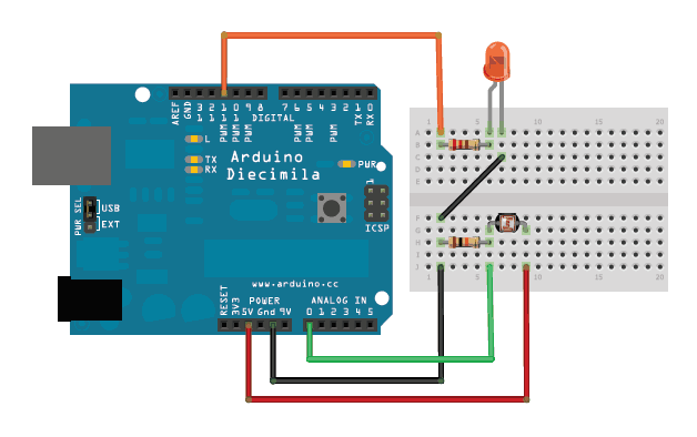
/*Photocell simple testing sketch.
Connect one end of the photocell to 5V, the other end to Analog 0.
Then connect one end of a 10K resistor from Analog 0 to ground
Connect LED from pin 9 through a resistor to ground
For more information see www.ladyada.net/learn/sensors/cds.html */
int photocellPin = 0; // the cell and 10K pulldown are connected to a0
int photocellReading; // the analog reading from the sensor divider
int LEDpin = 9; // connect Red LED to pin 09(PWM pin)
int LEDbrightness; //
void setup(void)
{
// We'll send debugging information via the Serial monitor
Serial.begin(9600);
}
void loop(void)
{
photocellReading = analogRead(photocellPin);
Serial.print("Analog reading = ");
Serial.println(photocellReading); // the raw analog reading
// LED gets brighter the darker it is at the sensor
// that means we have to -invert- the reading from 0-1023 back to 1023-0
photocellReading = 1023 - photocellReading;
//now we have to map 0-1023 to 0-255 since thats the range analogWrite uses
LEDbrightness = map(photocellReading, 0, 1023, 0, 255);
analogWrite(LEDpin, LEDbrightness);
delay(100);
}
LED Project - due 12 March 2010 - Fritz breadboard

I did a Fritz BreadBoard diagram,
but i could only make the BB view work.
The associated schematic was a real schemozzle, & every time i tried to fix it,
the wretched thing kept adding wires to my BB & i couldn't make them go away
without deleting the BB wires.. {siigh}.
As for the PCB view.. (duh!)
09 March 2010
Task 24 - ladyada - CDS cell diagram
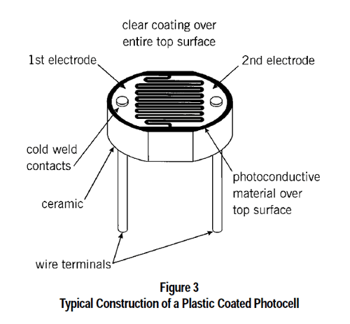
Here's a diagram of a cds (cadmium suphide) photocell
And this is the ladyada sensors site.
Nice explanations - very clear, nice tidy site. Not full of visual pollution & other techno-riffraff
Task 23 - wikieducator.org
HowManyArduinos
Meh!!
Yes i looked.. couldn't understand a thing!!
Haven't got a blue's clue.. never bothered with wikis before.
Tried a few things to put an entry in - nothing made any sense..
08 March 2010
LED Project - due 12 March 2010 - software
/*
* Project: LED-Project_3-LED-blinks_12mar10
* Author: Jane-Maree Howard
* Date: Monday 08/03/2010
* Platform: Arduino 18
* Purpose: To demonstrate variable blink times for external 3-colour LED
* Operation: Sets up output pins (4 off) in setup() method;
* Declares pin definition variables (4 off)
* Defines loop() to perform various LED blinking & delay operations
* Here we use a 3-colour LED and first turn them all ON, then OFF.
* Then we successively blink the RED, GREEN & BLUE
* LEDs, each with the same delay time, which ramps
* from 10ms up to 200 millisec & back down again.
* Here we use two 'for-loops': one to ramp up the Delays, &
* the other to ramp them back down again
*/
int ledPin = 13; // on-board LED connected to digital pin 13
int redLedPin = 12; // RED LED connected to digital pin 12
int grnLedPin = 11; // GREEN LED connected to digital pin 11
int bluLedPin = 10; // BLUE LED connected to digital pin 10
// the variable delay is accomplished by..
int iMult; // ..the multiplier variable multiplied by..
int dLay = 10; // ..the delay variable, which is 10 milliseconds
// The setup() method runs once, when the sketch starts
void setup()
{
// initialize the 4 digital pins as outputs:
pinMode(ledPin, OUTPUT);
pinMode(redLedPin, OUTPUT); // Red LED output
pinMode(grnLedPin, OUTPUT); // Green LED output
pinMode(bluLedPin, OUTPUT); // Blue LED output
// turn on the on-board LED & wait 0.5 seconds
digitalWrite(ledPin, HIGH); // turn on-board LED on
delay(dLay*50); // delay 0.5 seconds (50 * 10ms)
}//end setup()
// Loop first turns all 3 LEDs on succesively, then turns them off again.
// Delay between each phase is about 100 milliseconds
// Loop now turns RED, GREEN & BLUE LEDs on & off cyclically
// with varying delay each time loop runs, &..
// ..repeats endlessly while Arduino has power
// At the half-way point the order of the LED-cycle is reversed;
// Viewers should try to spot this point! What indicates this?
void loop()
{
digitalWrite(redLedPin, HIGH); // turn red LED on
delay(50*dLay); // delay 500 milliseconds
digitalWrite(grnLedPin, HIGH); // turn green LED on
delay(50*dLay); // delay 500 milliseconds
digitalWrite(bluLedPin, HIGH); // turn blue LED on
delay(100*dLay); // delay 1 second
// Now turn them all off..
digitalWrite(redLedPin, LOW);
digitalWrite(grnLedPin, LOW);
digitalWrite(bluLedPin, LOW);
delay(50*dLay); // ..& wait 0.5 seconds
// Ramps delays UP - Red, Green & Blue LEDs each turn on, then off,
// with the delay time increasing with each for-loop cycle
// from 10 - 200 milliseconds
for (iMult=1; iMult<=20; iMult++ ) // now start 'increasing delay' for-loop { digitalWrite(redLedPin, HIGH); // turn red LED on.. delay(iMult*dLay); // ..delay 10millisec * multiplier.. digitalWrite(redLedPin, LOW); // ..turn red LED off &.. digitalWrite(grnLedPin, HIGH); // ..turn green LED on.. delay(iMult*dLay); // ..delay 10millisec * multiplier.. digitalWrite(grnLedPin, LOW); // ..turn green LED off &.. digitalWrite(bluLedPin, HIGH); // ..turn blue LED on.. delay(iMult*dLay); // ..delay 10millisec * multiplier.. digitalWrite(bluLedPin, LOW); // ..turn blue LED off delay(iMult*dLay); // ..delay 10millisec * multiplier. }//end for(iMult++) // Ramps delays DOWN again - Blue, Green & Red LEDs each turn on, then off, // with the delay time decreasing with each for-loop cycle // Note REVERSED ORDER now Blue-Green-Red for (iMult=20; iMult>=1; iMult-- ) // now start 'decreasing delay' for-loop
{
digitalWrite(bluLedPin, HIGH); // ..turn blue LED on..
delay(iMult*dLay); // ..delay 10millisec * multiplier..
digitalWrite(bluLedPin, LOW); // ..turn blue LED off
delay(iMult*dLay); // ..delay 10millisec * multiplier..
digitalWrite(grnLedPin, HIGH); // ..turn green LED on..
delay(iMult*dLay); // ..delay 10millisec * multiplier..
digitalWrite(grnLedPin, LOW); // ..turn green LED off &..
digitalWrite(redLedPin, HIGH); // ..turn red LED on..
delay(iMult*dLay); // ..delay 10millisec * multiplier..
digitalWrite(redLedPin, LOW); // ..turn red LED off &..
delay(iMult*dLay); // ..delay 10millisec * multiplier
}////end for(iMult--)
//..& repeat
}//end loop()
LED Project - due 12 March 2010
* In this project, i use a 3-colour LED
* and first turn them all ON, then OFF.
* Then i successively blink the RED, GREEN & BLUE
* LEDs, each with the same delay time, which ramps
* from 10ms up to 300 millisec & back down again.
* Here i use two 'for-loops': one to ramp up the Delays, &
* the other to ramp them back down again.
* Loop first turns all 3 LEDs on succesively,
* then turns them off again.
* Delay between each phase is about 100 milliseconds
* Loop now turns RED, GREEN & BLUE LEDs on & off
* cyclically with varying delay each time loop runs, &..
* ..repeats endlessly while Arduino has power.
* I hope (!!) to post a video of the project running (soon)
* At the half-way point the order of the LED-cycle is reversed;
* Viewers could try to spot this point!
* What indicates this?
Video
Task 22 - Alternate Red/Yellow LEDs blinking, writing "Red "/"Yellow " to Serial Monitor at each blink
/*
* Project: Blink2-task 22
* Author: Jane-Maree Howard
* Date: Monday 08/03/2010
* Platform: Arduino 18
* Purpose: To demonstrate blink time for two external LEDs,
* & writing to the Serial Monitor (SM)
* Operation: Sets up 2 output pins in setup() method;
* Declares 2 pin definition variables, for red & yellow LEDs;
* Sets up output to serial port & thus to SM
* Each differently-coloured LED blinks alternately,
* & the word "Red " or "Yellow " is written to the SM @ each blink..
* .. & repeat
*/
int ylwLedPin = 12; // yellow LED connected to digital pin 12
int redLedPin = 11; // red LED connected to digital pin 11
int dLay = 200; // delay variable
// The setup() method runs once, when the sketch starts
void setup()
{
//Now open the serial port..
Serial.begin(9600); // ..& set data transmission rate to SM at 9600Baud
// initialize digital pins 11 & 12 as outputs
pinMode(redLedPin, OUTPUT);
pinMode(ylwLedPin, OUTPUT);
}//end setup()
// Loop turns red LED (pin 11) on, prints the word "Red " to the SM,
// waits 200 milliseconds, turns red LED off,
// turns yellow LED on, prints the word "Yellow " to the SM,
// waits 200 milliseconds, turns yellow LED off, &..
// ..repeats endlessly while Arduino has power
void loop()
{
digitalWrite(redLedPin, HIGH); // turn red LED on
Serial.print("Red "); // print the word "Red " to SM
delay(200); // delay 200 milliseconds
digitalWrite(redLedPin, LOW); // then turn red LED off;
digitalWrite(ylwLedPin, HIGH); // turn yellow LED on,
Serial.print("Yellow "); // print the word "Yellow " to SM,
delay(200); // delay 200 milliseconds,
digitalWrite(ylwLedPin, LOW); // turn yellow LED off
}//end loop()
Task 21 - writing "Blink" to the Serial Monitor
/*
* Project: Blink2-task 21
* Author: Jane-Maree Howard
* Date: Monday 08/03/2010
* Platform: Arduino 18
* Purpose: To demonstrate blink time for external LED & writing to the Serial Monitor (SM)
* Operation: Sets up output pin in setup() method;
* Declares pin definition variable;
* Sets up output to serial port & thus to SM;
* The LED blinks & the word "Blink" is written to the SM @ each blink..
* & repeat
*/
int redLedPin = 11; // red LED connected to digital pin 11
int dLay = 1000; // delay variable
// The setup() method runs once, when the sketch starts
void setup()
{
//Now open the serial port..
Serial.begin(9600); // ..& set data transmission rate to SM at 9600Baud
// initialize digital pin 11 as output
pinMode(redLedPin, OUTPUT);
}//end setup()
// Loop turns red LED (pin 11) on, prints the word "Blink" to the SM,
// waits one second, turns red LED off, waits one second &..
// ..repeats endlessly while Arduino has power
void loop()
{
digitalWrite(redLedPin, HIGH); // turn red LED on
Serial.println("Blink"); // print to SM
delay(200); // delay 200 milliseconds
digitalWrite(redLedPin, LOW); // then turn red LED off
delay(200); // delay 200 milliseconds
}//end loop()
06 March 2010
Task 20 revised - ramping the LED rate UP then DOWN again
/*
* Project: Blink2-Task 20 revised
* Author: Jane-Maree Howard
* Date: Saturday 06/03/2010
* Platform: Arduino 18
* Purpose: To demonstrate variable blink times for external LEDs
* Operation: Sets up output pins (3 off) in setup() method;
* Declares pin definition variables (3 off)
* Defines loop() to perform various LED blinking & delay operations
* In this case, there is a varying blink rate of the Yellow LED,
* from 10ms up to 1 sec & back down again.
* Here we use two 'for-loops': one to ramp up the Delays, &
* the other to ramp them back down again
*/
int ledPin = 13; // on-board LED connected to digital pin 13
int ylwLedPin = 12; // yellow LED connected to digital pin 12
int redLedPin = 11; // red LED connected to digital pin 11
int dLay = 10; // delay variable - now 10 milliseconds
// The setup() method runs once, when the sketch starts
void setup()
{
// initialize the 3 digital pins as outputs:
pinMode(ledPin, OUTPUT);
pinMode(ylwLedPin, OUTPUT);
pinMode(redLedPin, OUTPUT);
// turn on the on-board LED & wait 4 seconds
digitalWrite(ledPin, HIGH); // turn on-board LED on
delay(dLay*400); // delay 4 seconds (400 * 10ms)
}//end setup()
// Loop turns yellow LED (pin12) off, red LED (pin 11) on, waits 2 seconds,
// turns red LED on (or off) & runs a 'for-loop' 100 times:
// turn yellow LED on & off, with varying delay each time loop runs, &..
// ..repeats endlessly while Arduino has power
void loop()
{
//Ramps delays UP - Red LED stays ON thru Yellow LED loop
digitalWrite(ylwLedPin, LOW); // turn yellow LED off
digitalWrite(redLedPin, HIGH); // turn red LED on & leave it ON
delay(200*dLay); // delay 2 seconds
for (int i=1; i<=100; i++ ) // now start 'YellowLED for-loop' { digitalWrite(ylwLedPin, HIGH); // NOW turn yellow LED on.. delay(i*dLay); // ..delay 10millisec * multiplier.. digitalWrite(ylwLedPin, LOW); // ..turn yellow LED off.. delay(i*dLay); // ..delay 10millisec * multiplier.. }//end for(i..) digitalWrite(redLedPin, LOW); // turn red LED off now //Ramps delays DOWN again - red LED blinks.. digitalWrite(ylwLedPin, LOW); // turn yellow LED off digitalWrite(redLedPin, HIGH); // turn red LED on delay(200*dLay); // delay 2 seconds digitalWrite(redLedPin, LOW); // First turn red LED off for (int i=100; i>1; i-- ) // now start 'YellowLED for-loop'
{
digitalWrite(ylwLedPin, HIGH); // NOW turn yellow LED on..
delay(i*dLay); // ..delay 10millisec * multiplier..
digitalWrite(ylwLedPin, LOW); // ..turn yellow LED off..
delay(i*dLay); // ..delay 10millisec * multiplier..
}//end for(i..)
//..& repeat
}//end loop()
I really do think this is closer to the mark..
Subscribe to:
Posts (Atom)
