31 May 2010

Minor Project - external EEPROM management: software

/*
* Project: Minor_Project_I2C_24LC08_eeprom
* Author: Lewis Loflin:
for the original software & other details go to
http://www.sullivan-county.com/ele/arduino_24lc08.htm
* Date: Tuesday 23/02/2010 (Lewis's post)
* Modified: Jane-Maree Howard
* Comments: Jane-Maree is using this as a Minor Project,
with the following differences:
* The Arduino Duemilanove is based on the ATmega328 microcontroller.
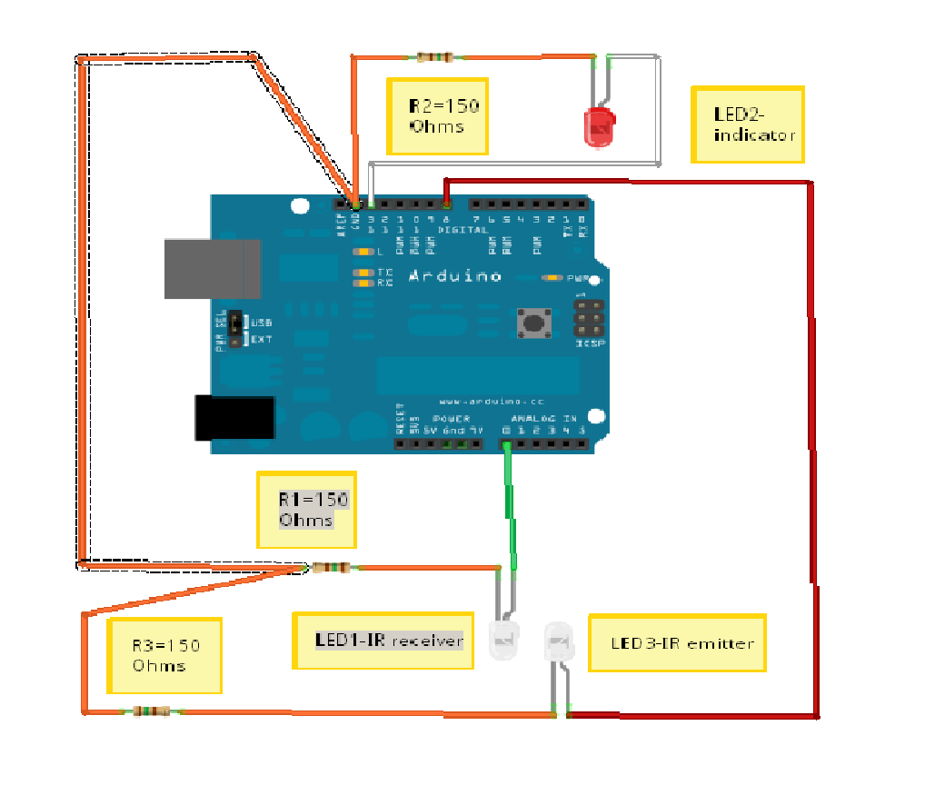
* The Fritzing diagram of the circuitry employing this software shows
two 24LC08 serial EEPROM chips in tandem on the same 2-wire interface.
* The software does not use all of the 2048 bytes available,
but it could be modified to do this e.g. to write the word "Arduino"
repeatedly until it fills the available EEPROM space.
* The word "Arduino" has seven characters; by counting the characters,
of your stored message/data, you can arrive at the number of bytes
the external EEPROM will send on request, since 1 byte stores 1 character.
You could retrieve all or part of the stored message/data as desired.
Note the modification to the original.
* Platform: Arduino 18
* Purpose: 24LC08 Demo with the ATMEGA128
This is an 8-pin DIP serial EEPROM.
It will store 1024 bytes. (0x3FF)
It uses I2C or "two wire" interface.
* Operation: On power up or reset the "setup" is executed once,
setting up the hardware and writing the text message "Arduino" to the EEPROM.
Then the "loop" section will run over and over.
Whenever sw0 is pressed the text message "Arduino" is read from the EEPROM
and sent via the serial port to a computer running for example Hyper Terminal.
This demonstrates the use of the Wire.h library,
serial ports, and an external switch tied to an input.
Pin designations for the 24LC08:
Pins 1, 2, 3:
if tied to VCC (5 volts) address = 0x54;
if tied to VSS 0x50.
Only two can be used in a single circuit.
Pin 4 VSS or ground.
Pin 5 SDA or serial data. Tied to Arduino analog pin 4.
Pin 6 SCL or serial clock. Tied to Arduino analog pin 5.
Pin 7 WP or write protect. VCC disables write, VSS enables write.
Pin 8 VCC or +5 volts.
*/

#include Wire.h// specify use of Wire.h library.

byte sw0 = 12; // digital pin for switch connected to ground.
int position_pointer = 0x3f0; // address in 24LC08. Values from 000 hex to 3FF hex.

void setup()
{
pinMode(sw0, INPUT);
digitalWrite(sw0, HIGH); // turn on internal pull up
Wire.begin(); // join i2c bus (address optional for master)
Serial.begin(9600); // setup serial for output

// send test message "Arduino"
Wire.beginTransmission(0x50); // connect to 24LC08 device address
Wire.send(position_pointer); // beginning address within EEPROM (0x3f0)
Wire.send("me");
//Wire.send("Arduino");
Wire.endTransmission();
}//end setup()

void loop()
{
//digitalWrite(sw0, HIGH); // turn on internal pull up
while (digitalRead(sw0) == 1)
{} // wait here until switch is pushed.
Wire.beginTransmission(0x50); // link to 24LC08
Wire.send(position_pointer); // must act as a position pointer
Wire.endTransmission();
Wire.requestFrom(0x50, 5); // request 7 bytes from slave device 24LC08

// below will loop until 5 bytes are received.
while(Wire.available()) // slave may send less than requested
{
byte c = Wire.receive(); // receive a byte as character
Serial.print(c); // print the character
}//while()
Serial.print("\n"); // next line
delay(2000); // wait one second.
}//end loop()


//*****************************************************SEE VERY IMPORTANT COMMENT BELOW

26 May 2010

Minor Project - external EEPROM management: Fritzing diagram


Looking a whole lot tidier than my usual efforts.

I decided to use the Breadboard icon & assemble everything on there - so it's very much a WYSIWYG diagram; just wire up a breadboard as in the diagram (i've got one of those big ones with the side rails - had it it for 30 years or more, & i thought i'd lost it (whew!!)).

No imagination or interpretation needed; i even colour-coded the wiring to match the stuff i got in my MindKit starter pack (lots of Orange leads for some reason..). Given that it's Stupid O'clock in the morning
right now, the less thinking i have to do the better!

I'll post some Serial Monitor output later - i'd like to experiment with variations on the basic design so as to illustrate the actual 2-wire goings-on,
like requesting half a message,
or a specified part of it,
or varying start-addresses, message-length & the like

Once i get that sussed, Data-logging should be a treat!

(Regretably, that never happened. And i had to 'debug' the breadboard as well)

23 May 2010

Minor Project - external EEPROM management: - more diagrams


Above top is the pinout diagram for the 24xx256, & below that is how the 24LC08 is connected to the Arduino. The pinout's the same anyway..
Note that Analog pins 4 & 5 are used for the I2C communication, so they can't be used for any other purpose.
Pull-up resistors R1 & R2 are 10 kilOhms.

It's all fairly simple really (she says, crossing her fingers & toes)..
Hard-wiring a shield is now fairly simple - i just have to Stop Procrastinating!!

The other pins can be used for breadboarded inputs & outputs - for inputs from the 'Great Weekend Datalogging Project' - more about that later..

This program has been revisited.

20 May 2010

Minor Project - external EEPROM management: shield

A shield for my Minor Project includes DIL sockets for 2 external EEPROMs & various connections for hooking them up to the basic Arduino.
I hope to be able to provide a +5v 'rail' and a Ground (0v) 'rail' to minimise the tangle of connectors which currently bedevils most of my hardware.

Minor Project - external EEPROM management: some schematic data


The Fritzing diagram for my Minor Project shouldn't be very complicated - it's basically connecting two external 8-pin DIP-packaged external EEPROM chips to the basic Arduino board so that write/read operations can proceed.

On the left is the 24LCxx pinout table.
This is nice because it means i can swap the
24LC08 chips i have now for, say, 24LC256 chips, & all i need to do is change a bit of software!


Just above is how you connect several external EEPROMs on the same I2C bus - each has a connection to the SCL line & the SDA line..


Minor Project - external EEPROM management: software from Nicholas Zambetti; his WIRE library


This is the wire library!


Some very nice & simple stuff from Nicholas Zambetti.
Just needs adapting for what i want - which isn't complicated..


/*
Wire Master Writer by Nicholas Zambetti

Demonstrates use of the Wire library
Writes data to an I2C/TWI slave device
Refer to the "Wire Slave Receiver" example for use with this
*/

#include Wire.h

void setup()
{
Wire.begin(); // join i2c bus (address optional for master)
}//setup()

byte x = 0;

void loop()
{
Wire.beginTransmission(4); // transmit to device #4
Wire.send("x is "); // sends five bytes
Wire.send(x); // sends one byte
Wire.endTransmission(); // stop transmitting

x++;
delay(500);
}//loop()

//==============================================

/*
Wire Slave Receiver by Nicholas Zambetti

Demonstrates use of the Wire library
Receives data as an I2C/TWI slave device
Refer to the "Wire Master Writer" example for use with this
*/
#include Wire.h

void setup()
{
Wire.begin(4); // join i2c bus with address #4
Wire.onReceive(receiveEvent); // register event
Serial.begin(9600); // start serial for output
}//setup()

void loop()
{
delay(100);
}//loop()

// function that executes whenever data is received from master
// this function is registered as an event, see setup()
void receiveEvent(int howMany)
{
while(1 < c =" Wire.receive();" x =" Wire.receive();">

//========================================

/*
Wire Master Reader by Nicholas Zambetti

Demonstrates use of the Wire library
Reads data from an I2C/TWI slave device
Refer to the "Wire Slave Sender" example for use with this

*/
#include Wire.h

void setup()
{
Wire.begin(); // join i2c bus (address optional for master)
Serial.begin(9600); // start serial for output
}// setup()

void loop()
{
Wire.requestFrom(2, 6); // request 6 bytes from slave device #2

while(Wire.available()) // slave may send less than requested
{
char c = Wire.receive(); // receive a byte as character
Serial.print(c); // print the character
}//while()

delay(500);
}//loop()

//===========================================

/*
Wire Slave Sender by Nicholas Zambetti

Demonstrates use of the Wire library
Sends data as an I2C/TWI slave device
Refer to the "Wire Master Reader" example for use with this
*/
#include Wire.h

void setup()
{
Wire.begin(2); // join i2c bus with address #2
Wire.onRequest(requestEvent); // register event
}//setup()

void loop()
{
delay(100);
}//loop()

// function that executes whenever data is requested by master
// this function is registered as an event, see setup()
void requestEvent()
{
Wire.send("hello ");
// respond with message of 6 bytes as expected by master
}//requestEvent()


//*****************************************************SEE VERY IMPORTANT COMMENT BELOW

Tasks 46 & 47 - Communication between Arduinos - Fritzing breadboard

Tasks 46 & 47 - Communication between Arduinos

14 May 2010

Task 51 - basic EEPROM program & screeen dump


There's the Screen Dump onto the Serial Monitor.

Note the first value - 105.
Don't know why that should be, since all the others are 255, as expected because the default content is hFF, i.e. decimal 255.

Now to move on..

Task 51 - basic EEPROM program & screeen dump: software

/*
below is the no-frills EEPROM program.
i'll make a nicer, tidier one later on..
*/


#include EEPROM.h


int a = 0;
int value;

void setup()
{
Serial.begin(9600);
}

void loop()
{
value = EEPROM.read(a);

Serial.print(a);
Serial.print("\t");
Serial.print(value);
Serial.println();

a = a + 1;

if (a == 512)
a = 0;

delay(500);
}

/*
VERY IMPORTANT!!
In the above codings there are
#include EEPROM.h
statements.
Around the EEPROM.h there should be 'less-than' &
'greater-than' symbols.
these don't show up in these blog postings..
..don't forget them!
*/

Tasks - & the Moral of the story is..


..don't overload on carbs the night before your Presentation is due!

Umm, yes, well, 2 bowls of VelvetBurger's chips & sauce (garlic mayo), Plus
(later on) a Domino's (No i'm NOT getting paid to say this!) Double-Bacon-&-Cheese pizza..

..this morning everything was clogged up:
my head (felt like a lump of pizza base);
Port Chalmers main street (with roadworks & a Stop-Go man);
the Open Access suite (with students);
the Internet (with people trying to get online)..

I'd actually gotten up, dressed, got my stuff together ready to walk out the door, then thought:
"i'm feeling a bit tired; i think i'll just have a lie-down.."

..about 2pm i surfaced rapidly ("blow main ballast - aaooogah!" - been reading submarine warfare stories), & realised that i'd completely missed the morning's work, that i had better get A into G, & email Peter B with my PowerPoint (i use Open Office Impress @home - it's FREE! So is Belarc Advisor - a very useful little diagnostic app) & explain that i really had it all ready for the morning's lecture..

(sigh)

Maybe i can do that now, & then have a go at more Tasks.

13 May 2010

Task 53+ - Software Syntax Presentation...

I've got my Syntax Presentation all ready, on the following:

Comparison Operators;

Boolean Operators;

I Think i'm supposed to do the Bitwise Operators (ummm.. i don't actually Know)

Compound Operators.

There's quite a bit of stuff there..
..but i'm getting reasonably good at PowerPoints now, tho' i'm still functionally illiterate visually, so there are no pretty pictures or fancy backgrounds.

There was some controversy about PPs a while back, to the effect that some important technical PPs had so much distracting visual frippery that vital technical points were being glossed over & nobody noticed until some disaster or other happened further down the track.

Then everybody's lawyers got busy with 'perms & coms' of lawsuits against everyone except God..
..& a really really good time was had by a few.

Poor old Joe & Jane Pleb just hefted the bill (as ever) in the form of higher prices for this-that-&-the-other while the goof-balls made up their own versions of The Truth & concentrated on clawing back as much foregone income as poss..

(sigh) plus ca change!

10 May 2010

Task 45 - Infra-Red (IR) Send and Receive Software

Well this was the software for Task 45..
..would've been nice if it'd all worked!

/*
* Project: Task 45_IRxMitRecv
* Author: Jane-Maree Howard
* Date: Friday 30/04/2010
* Platform: Arduino 18
* Purpose: To demonstrate variable blink communication
between an infra-red(IR)-LED & an IR-receiver diode.
* Operation: Description:
Connect the IR-receiver diode's anode to +5V,
& its cathode to Analog 0.
Connect the IR-LED's anode to pin 12,
& its cathode through a resistor to ground.
Connect a LED from pin 9 through a resistor to ground.
Declare: 4 pin definition variables, pin-state(HIGH/LOW) vble,
delay vble, analog reading vble, & output brightness vble.
Setup(): output pins (2 off) & the IR input pin;
Loop(): perform various IR-LED transmit/receive operations.
*/

byte obLedPin = 13; // on-board LED as indicator
byte irLedPin = 12; // infra-red LED connected to digital pin 12
byte LEDpin = 9; // connect a LED to pin 09(PWM pin) - output
byte recLedPin = 0; // receiving LED connected to analog pin 0 (a0)
int dLay = 1000; // delay variable
int recLedVal; // the analog reading from the IR-sensor
byte LEDbrightness; // pin 09 output LED brightness
byte pinState; // pins 12 & 13 HIGH/LOW state

void setup()
{
pinMode(obLedPin, OUTPUT); // digital pin 13 as output:
pinMode(irLedPin, OUTPUT); // digital pin 12 as output:
digitalWrite(obLedPin, HIGH); // turn on-board LED on
delay(dLay*4); // wait 4 seconds
Serial.begin(9600); // set up Serial Monitor
}//end setup()

void loop()
{
// transmit
pinState = 1; // pins 12 & 13 HIGH state
irSendReceive(pinState); // IR-LED & ob-LED ON

// don't transmit
pinState = 0; // pins 12 & 13 LOW state
irSendReceive(pinState); // IR-LED & ob-LED OFF
}//end loop()

// IR Send-Receive routine
void irSendReceive(byte pState)
{
digitalWrite(obLedPin, pState); // turn on-board LED on/off
digitalWrite(irLedPin, pState); // turn IR-LED on/off
recLedVal = analogRead(recLedPin); // read IR receiver diode &..
irResultOut(recLedVal); // ..send result to Serial Monitor & brightness LED
delay(dLay); // wait 1 second
}//irSendReceive()

// Serial Monitor print routine
void irResultOut(int pVal)
{
//now we have to map 0-1023 to 0-255
//since that's the range analogWrite() uses
LEDbrightness = map(pVal, 0, 1023, 0, 255);
analogWrite(LEDpin, LEDbrightness);
Serial.print("IR value is ");
Serial.print(pVal);
if (pVal > 770)
{
Serial.println(" - HIGH");
}//if()
else
{
Serial.println(" - ***LOW***");
}//else..
}//irResultOut()

08 May 2010

Task 5 - 4 LED videos


How to Multiplex with LEDs


Realistic LED Flickering Flame Effect using an Arduino


Yet Another Electronic (LED) Flickering Candle


LED Pixel Matrix Project

Embedded Notices, Chip8News, Sanguino

Embedded Notices 1-53

Chip8News

(just for my benefit)

And some more Chip-8 links..
More Chip8
CHIP-8 on Wikipedia
wikieducator Chip8

& Sanguino

Tasks 1-3 & 6 VeryBasicStuff


1. Well, here's the blog
2. And this is
Moodle @ Otago Polytechnic

3. Above-screenshot of my profile..
6. Just look through TASKs

Task 42 - a few YABBrules


There seem to be very few rules for YABB,
but a few could be:
No Spam
No Commercials (adverts)
No 'foul' language
No personal abuse
No 'flame wars'..
..that's the 'No's out of the way..
Be nice, & friendly
Try to be helpful & constructive
(& this isn't a rule as such but..
contribute if you can
:-) :-) :-)

Task 45 - Infra-Red (IR) Send and Receive


Well, i've made a breadboard Fritzing diagram.
You can export a Fritz-bb as a JPEG, PNG, to a .pdf
& other options - much easier than messing about
with unwieldy stuff like Flash etc [snore]..

07 May 2010

Task 45 - Infra-Red (IR) Send and Receive


Well i have some software ready - the first one i tried was a dud!
This one originally came from

http://www.arduino.cc/playground/Learning/Tachometer

but needed a bit of adapting..

..& it's NOT working!
I've got a feeling it's the hardware..