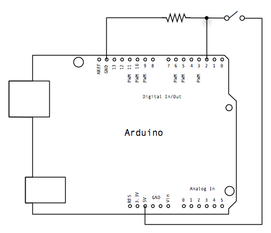
 The circuit is quite simple - pin 2 is pulled down to 0V through the 10k pull-down resistor, until the button is closed. This pulls pin 2 up to +5V, & this causes pin 13 to go HIGH & light up the on-board LED.
The actual push-button has 4 terminals, but they are paired, (as is evident on the breadboard).

No comments:
Post a Comment